Crush Pipe Problem
Crush Pipe Problem. MSC.Patran 2005 r2 MSC.Marc 2005 r2. Estimated Time for Completion: ~35min Experience Level: Lower. Topics Covered. Topics covered in Modeling Creating Shell elements by extruding Beam elements

Crush Pipe Problem
E N D
Presentation Transcript
Crush Pipe Problem MSC.Patran 2005 r2 MSC.Marc 2005 r2 Estimated Time for Completion: ~35min Experience Level: Lower
Topics Covered • Topics covered in Modeling • Creating Shell elements by extruding Beam elements • This is the easiest way to make a 3-D shell structure that has uniform cross section. • Creating Elastic-perfectly plastic material • The material non-linearity is approximated by a constant • Applying Equivalence to the redundant nodes. • Equivalence eliminates any duplicated nodes and cracks created by the mesher. • Topics covered in Analysis • Applying Deformable and rigid bodies contact • Applying Large Displacement/Large Strains Analysis • Applying Modified Riks/Ramm method • One of the Increment types which can solve problems with complicate nonlinearity or post-buckling. • Modifying Contact Table • The contact condition for each contact pair can be modified.
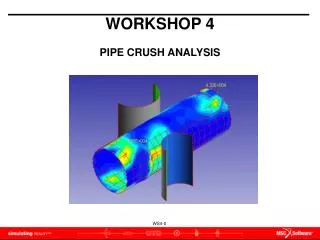
Problem Description Move 2in in the -Y R=5 Pipe D=8 Move 2in in the +Y R=3 20 10 • A contact between a rigid body and a deformable body is often used in many applications. In this example, A hollow pipe is crushed by moving three rigid cylinders. The rigid cylinders push the pipe surface to a total stroke of 2 inches. Both ends of the pipe are fixed. The material is elastic-perfectly plastic. Rigid – deformable, surface-to-surface contacts
Problem Description R=5 Move 2in in the -Y Pipe D=8 Move 2in in the +Y 10 R=3 20 • In this example problem, we apply Symmetric boundary conditions at the center of the pipe to reduce the number of elements and the analysis time. The following condition is applied at the boundary. • ux=θy= θz=0 on the symmetric boundary • We will model Elastic-perfectly plastic material properties to simplify the plasticity of the material.
Summary of Model • Rigid bodies • Diameters: • Upper=5in, Lower=3in • Motion: • 2in toward the center of the pipe • Steel pipe • Dimensions: • Diameter=8in, • Length=40in, • Thickness=0.5in • Material properties: • Young’s Modulus =30.0x10⁶psi, • Poisson’s ratio=0.3, • Yield strength=36000 psi
Goal • We will determine the maximum von Mises stress and find the location in the pipe.
Expected Results • von Mises Stress • Displacement, Translation(Magnitude)
Create Database a d e b c f g h i • Click File menu / Select New • In File Name enter crushed_pipe.db • Click OK • Select Analysis Code to be MSC. Marc • Click OK • Click Group menu / Select Create • In New Group Name enter rigid • Check Make Current • Click Apply
Create Rigid Bodies p f a b c d e g h i j k l m n o Create a curve for the rigid body below the pipe • Click Geometry icon • Select Action to be Create • Select Object to be Point • Select Method to be XYZ • Uncheck Auto Execute • In Point Coordinates List, enter [10,-7.1,4.5] • Click Apply • In Point Coordinates List, enter [13,-7.1,4.5] • Click Apply • Select Object to be Curve • Select Method to be Revolve • In Axis, enter {Point 1[X1 Y1 5.0]} • In Total Angle, enter 180 • Uncheck Auto Execute • In Point List, enter Point 2 (or select Point 2) • Click Apply
Create Rigid Bodies a b c d e f g h i j k l Create a curve for the rigid body below the pipe • Select Object to be Point • Select Method to be XYZ • In Point Coordinates List, enter [0,9.1,4.5] • Click Apply • In Point Coordinates List, enter [5,9.1,4.5] • Click Apply • Select Object to be Curve • Select Method to be Revolve • In Axis, enter {Point 4[X4 Y4 5.0]} • In Total Angle, enter -90 • In Point List, enter Point 5 (or select Point 5) • Click Apply
Create Deformable Body s r a b c d e f g h i j k l m n o p q Create a curve for the deformable body • Click Group menu / Select Create • In New Group Name enter pipe • Check Make Current • Select Group Contents to be Add Entity Selection • Click Apply • Click Cancel • Select Action to be Create • Select Object to be Point • Select Method to be XYZ • In Points Coordinates List, enter [0,0,0] • Click Apply • In Points Coordinates List, enter [0,4,0] • Click Apply • Select Object to be Curve • Select Method to be Revolve • In Axis, enter {Point 7[1 Y7 Z7]} • In Total Angle, enter 360 • In Point List, enter Point 8 (or select Point 8) • Click Apply
Create Deformable Body q f a b c d e p g i j k l m n o h Create Mesh seed and Mesh on the deformable body h. Click Group menu / Select Create i. In New Group Name enter fem_pipe • Click Apply • Click Cancel • Select Action to be Create • Select Object to be Mesh • Select Type to be Curve • Select Topology to be Bar2 • In Curve List, enter Curve 3 • Click Apply • Click Element icon • Select Action to be Create • Select Object to be Mesh Seed • Select Type to be Uniform • In Number, enter 20 • In Curve List, enter Curve 3 • Click Apply
Create Deformable Body a b c d e f g h Create surface elements of the deformable body by extruding the bar elements • Select Action to be Sweep • Select Object to be Element • Select Method to be Extrude • In Direction Vector, enter <20,0,0> • Check Delete Original Elements • In Base Entity List, enter Elm 1:20 • Or select the elements in the current viewport using the mouse left button • Click Apply Tip: Select the elements after clicking the icons and
Create Rigid Bodies u h a b c d e f g t i k l m n o p q r s j Create surface elements of the rigid bodies by extruding the bar elements • Click Group menu / Select Post • In Select Groups to Post, select rigid • Click Apply • Click Cancel • Select Action to be Create • Select Object to be Mesh • Select Type to be Curve • In Curve List, enter Curve 2 • Click Apply • In Curve List, enter Curve 1 • Click Apply • Select Action to be Sweep • Select Object to be Element • Select Method to be Extrude • Click Mesh Control • In Number, enter 1 • Click OK • In Direction Vector, enter <0,0,-10> • Check Delete Original Elements t. In Base Entity List, enter Elm 401:402 Or select all element using the left button of the mouse u. Click Apply
Applying Equivalence a b c d • Select Action to be Equivalence • Select Object to be All • Select Method to be Tolerance Cube • Click Apply This will eliminate any extra overlapping nodes created by the mesher. See below for the comparison. w/o Equivalence with Equivalence
Verifying the element Normals a b c d e f g h i j • Select Action to be Verify • Select Object to be Element • Select Test to be Normals • Select Display Control to be Draw Normal Vector • Click Apply The Element Normals should point towards the pipe (SEE below). if not, • Select Action to be Modify • Select Object to be Element • Select Method to be Reverse • In the Element List, enter the list of elements with the wrong directions. Or select them using the mouse left button • Click Apply Wrongdirections Correctdirections
Create a group for All FEM a b c d e f g h • Click Group menu / Select Create • Select Action to be Create • Select Method to be Select Entity • In New Group Name, enter fem_all • Check Make Current • Select Group Contents to be Add All FEM • Click Apply • Click Cancel
Create the Material Properties for the pipe g a b c d e f q h i j k l m n o p • Click Materials icon • Select Action to be Create • Select Object to be Isotropic • Select Method to be Manual Input • In Material Name, enter steel • Click Input Properties • Select Constitutive Model to be Elastic • In Elastic Modulus, enter 30e6 • In Possion Ratio, enter 0.3 • Click OK • Click Apply • Click Input Properties again • Select Constitutive Model to be Plastic • Select Type to be Perfectly Plastic • In Yield Stress, enter 36000 • Click OK • Click Apply
Create the Element Properties for the pipe q a b c d e f g h i j k l m n o p r • Click Group menu / Select Post • In Select Groups to Post, select fem_pipe • Click Apply • Click Cancel • Click Properties icon • Select Action to be Create • Select Object to be 2D • Select Type to be Thick Shell • In Property Set Name, enter pipe • Select Options to beHomogeneous andStandard Formulation • Click Input Properties • Click Mat Prop Name icon • Select steel • In [Thickness], enter 0.5 • Click OK • In Application Region, enter Elm 1:400 or select elements on the pipe using the mouse left button • Click Add • Click Apply
Create Boundary Conditions l f a b c d e g h i j k l m n o Create the Fixed Boundary Conditions • Click Loads/BCs icon • Select Action to be Create • Select Object to be Displacement • Select Type to be Nodal • In New Set Name, enter fixed_disp • Click Input Data • In Translations, enter <0,0,0> • In Rotations, enter <0,0,0> • Click OK • Click Select Application Region • Select Geometry Filter to be FEM • In Select Nodes, enter Node 421:440 or select the nodes on the fixed boundary using the mouse left button • Click Add • Click OK • Click Apply
Create Boundary Conditions k n a b c d e f g h i j k l m Create the Symmetric Boundary Conditions • Select Action to be Create • Select Object to be Displacement • Select Type to be Nodal • In New Set Name, enter sym_disp • Click Input Data • In Translations, enter <0, , > • In Rotations, enter < ,0,0> • Click OK • Click Select Application Region • Select Geometry Filter to be FEM • In Select Nodes, enter Node 1:20 or select the nodes on the symmetric boundary using the mouse left button • Click Add • Click OK • Click Apply
Create Boundary Conditions m p a b c d e f g h i j k l m n o Create the Contact Condition for the deformable body. • Click Group menu / Select Post • In the list, select fem-all • Click Apply • Click Cancel • Select Action to be Create • Select Object to be Contact • Select Type to be Element Uniform • Select Option to be Deformable Body • In New Set Name, enter contact_mid • Select Target Element Type to be 2D • Click Select Application Region • Select Geometry Filter to be FEM • In Select 2D Element, enter Elm 1:400 or select the elements on the pipe using the mouse left button • Click Add • Click OK • Click Apply
Create Boundary Conditions y j a b c d e f g h i x k m n o p q r s t u v w l Create the Contact Condition for the Rigid Bodies. • Select Action to be Create • Select Object to be Contact • Select Type to be Element Uniform • Select Option to be Rigid Body • In New Set Name, enter contact_top • Select Target Element Type to be 2D • Click Input Data • Select Motion Control to be Position • In Displacement (vector), enter <0,-2,0> • Click OK • Click Select Application Region • Select Geometry Filter to be FEM • In Select 2D Element, enter Elm 401:410 or select the elements on the upper rigid body using the mouse left button • Click Add • Click OK • Click Apply • In New Set Name, enter contact_bottom • Click Input Data • In Displacement (vector), enter <0,2,0> • Click OK • Click Select Application Region • In Select 2D Element, enter Elm 411:420 or select the elements on the lower rigid body using the mouse left button • Click Add • Click OK • Click Apply
Create Boundary Conditions n e a b c d f g h i j k l m Correct the Contact Normal for both rigid bodies. The Contact Normals should be shown as below • Select Action to be Modify • Select Object to be Contact • Select Type to be Element Uniform • Select Option to be Rigid Body • In Select Set to Modify, select contact_top • Click Modify Data • Check Flip Contact Side • Click OK • Click Apply • In Select Set to Modify, select contact_bottom • Click Modify Data • Check Flip Contact Side • Click OK • Click Apply
Run Analysis a b c d e f g h i j k l Run Analysis using Nonlinear Analysis Options • Click Analysis icon • Select Action to be Analyze • Select Object to be Entire Model • Select Method to be Full Run • In Job Name, enter crushed_pipe • Click Load Step Creation • In Load Step Name, enter Pipe_crush • Select Solution Type to be Static • Click Solution Parameters • Select Linearity to be NonLinear • Select Nonlinear Geometry Effects to be Large Displacement/Large Strains • Click Load Increment Parmas
Run Analysis a b c d e f g h i j k l m Run Analysis using Nonlinear Analysis Options • Select Increment Type to be Adaptive Arc Length • Select Arclength Method to be Modified Riks/Ramm • In Max # of Increments, enter 100 • Click OK • Click Iteration Parameters • In Max # of Iterations per Increment, enter 75 • Click OK • Click Contact Table • Click Glue All • Click OK • Click OK • Click Apply • Click Cancel
Run Analysis and Read Results a b c d f g h i j k l Run Analysis using Nonlinear Analysis Options • Select Load Step Selection • In Existing Load Steps, select Pipe_crush • In Selecte Load Step, click Default Static Step to deselect it. • Click OK • Click Apply Read Results File • Select Action to be Read Results • Select Object to be Result Entities • Select Method to be Attach • Click Select Results File • Select crushed_pipe.t16 • Click OK • Click Apply
Reviewing the Results a b c d e f g h i j k Review the Displacement Results • Click Results icon • Select Action to be Create • Select Object to be Quick Plot • In Select Result Cases, select the last results (with Time=1.0) • In Select Fringe Result, select Displacement, Translation • In Select Deformation Result, select Displacement, Translation • Click ApplyCheck the viewport to see the result plot • In Select Fringe Result, select Stress, Global System • Select Quantity to be von Mises • In Select Deformation Result, select Displacement, Translation • Click ApplyCheck the viewport to see the result plot
Results • von Mises Stress • The location of the maximum stress in the structure. σmax=4.69x10⁴ psi • Displacement, Translation(Magnitude)
Further Analysis (Optional) • Problem modification • Will removing the fixed boundaries change the location of the maximum stress? (This is the Pipe-bending problem) • Modeling • Instead revolving a point, what other methods you can use to draw circles? What is the advantage of revolving a point? • Solution options • Do the different values for Max # of Increments and Max # of Iterations per Increment make different results? • Try with other solution methods (increment types). Can you find any difference?