Download
1 / 44
440 likes | 461 Views
This update presents magnetic field engineering developments, including analysis of tracker shielding and waveguide positioning at IIT Craig Macwaters. Key topics covered include prototype construction, waveguide lengths investigation, positioning of cryostats, and shielding solutions for sensitive equipment such as the Weiner PSU and vacuum gauge. Detailed modelling insights and design considerations are discussed, with a focus on achieving optimal magnetic field protection and efficient equipment placement within the facility.

E N D
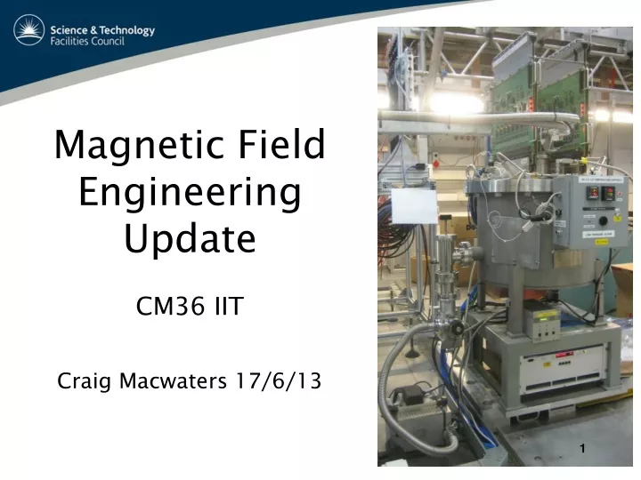
Magnetic Field Engineering UpdateCM36 IITCraig Macwaters 17/6/13
Contents… • Tracker shielding can analysis • Kiril Marinov (Daresbury) • Tracker shielding can prototype • Craig Macwaters • Tracker individual shields - KM • Integration engineering update • Jason Tarrant (RAL)
The tracker cryo problem… Field in AIR x-sect, looking upstream to Q9 ~600G CH Turbo Lid CCG ~400G Pink=100mT=1000Gauss ~250G PSU
Turbo side Front Many sensitive items… Cold Head ~350G AFE transformer ~800G Lid heater box ~15G (need to move ) Inverted Mag cold cathode gauge ~75G Turbo Controller ~150G Cooling fan Weiner PSU ~250G Turbo pump ~50G & Power fail valve
What about a big shielding can? 1.2M • Kiril Marinov at DL has worked on magnetic modelling and analysis and full details on modelling website • CM looked at physical Slot for waveguides 2M Slot for services
Step4 – Possible position of shielding cans – still many problems! x x x x X= original position of cryostats New positions approximately 70 to 80 cm further away Shielding can Pure Iron 120cm ID 200cm high 8+cm thick 7 Tonnes each
Position of south cryos • Cones represent centre of can • Radius approx 60cm • Takes up a lot of thoroughfare • Half On/Off platform • WAVEGUIDE LENGTHS!!
Investigating waveguide reach Spectrometer Solenoid model in MICE hall Old IC cryostat model
Henry trying to stretch the waveguides! Real size Cryostat model
Half height model 116cm diameter can – relatively large
Dummy waveguide routing • Tight routing – right on the limit and this is using empty conduit • Real waveguides will be stiffer with smaller bend radius • Could we tilt the can & cryostat?
Tr1? Tr2? Possible new position of tracker racks : Ovals show a 7M reach from both cryo pairs Tr2? Tr1? Tr2? Tr2? Tr1? 7M ovals allow a further 2.8M for vertical drops. Making 9.8M total for AFE backplane to VME crate for VLSB cables.
Baseline position for tracker racks (behind North Shield Wall)
Tracker rack1? Visualisation of rack behind NSW • Checked OK by fire officer • Very tight on VLSB cable lengths • Need to detail and model • Need to move RF Cage east gate
Tracker Shielding can summary • Heavy, 4 x 7 Tonnes! Floor load? • How easily can we move these big cans into and out from the beamline. Under south mezz would not be able to use the crane. Rails? • South cryo positions completely foul Jason’s compressor hose distribution • Cost 4 x £20K? • WAVEGUIDE lengths probably just too short. Could we angle the cryostats inwards? • Many issues so we decided to investigate local shielding…
Concept: a shielding box with a pair of “chimneys” Air outtake, inner diameter 60 mm, outer 80 mm, 60 mm high Top Binmax<<<B0 540X620X280 AISI 1010 5 mm thick steel Air intake, inner diameter 60 mm, outer 80 mm, 60 mm high
Design considerations • The “chimneys” serve several purposes… • Access for cabling • Bottom-to-top air convection • Possibility of additional fans or using compressed air • The position of the air intake/outtake pair does not need to be in the centre. If needed, a second pair could be a added. • There is a 50 mm gap between the PSU and the shield. This can be increased, but larger shielded volumes require thicker walls. • Heat loss needs to be quantified as it will affect the design
Method • The shield is placed between the poles of a window-frame magnet generating uniform field along Z of 30 mT • The shield has been rotated around its three main axes and assessed in each configuration • Weiner quote the PSU as able to tolerate up to 25 mT. In all the subsequent plots the external field is always along the Z axis.
External field parallel to the air in/outtake axis B(X=0,Y,Z) Approx 5mT
External field perpendicular to the air in/outtake axis B(X,Y,Z=0) Approx 13mT
PSU Shield Summary • Three orientations of the structure with respect to applied magnetic field have been considered. • With a typical external field of >30 mT the field inside the shielded area is well below the target value of 20 mT. • Better shielding can be achieved with thicker walls and longer chimneys. This design show satisfactory shielding with 5mm box. • A prototype should be built and tested. This will help with eliminating a number of uncertainties, e.g. model validation, effect of welding on the magnetic properties of the steel, assessing power dissipation etc. • Mechanically the box needs to be designed in such a way that opening and closing features do not affect the shielding performance.
Magnetic Shield for turbo pump and vacuum gauge - KM Leybold SL80 turbo pump. This is the area that requires shielding
Turbo shield design considerations • The external field is of the order of 40 mT. The pump can tolerate 5 mT, regardless of field direction. • The logical proposed solution is a 10 mm thick AISI 1010 capped cylinder, 300X110 mm. • Reducing the shielded volume reduces the wall thickness. Halving the shield height has a big impact on performance. • As discussed with Craig, dimensions will be finalized when/if the shields are engineered. Need to take account of backing line connection and cooling.
Turbo Shield Concept Φ60 Φ110 Capped lids with aperture 300mm ~8 kg 10 mm thick AISI 1010 steel
Installation The two halves can be held together by steel bands. The gap can be controlled by a thin gauge during assembly, should not be much bigger than 0.1 mm.
Turbo Shield Performance • Applied uniform field using window-frame magnet option in Opera. • The field inside the shielded area is below the 5 mT limit • The 220mm “safe” area can be extended further by 3-4 cm by a adding chimney. The external field is axial. The external field is radial B B 220mm ~1 mT ~0.5 mT
The vacuum gauge shield Φ50 Φ110 Φ70 200 150 10 mm thick AISI 1010 steel ~6 kg 50 The same cylinder as used for the pump, only 200 mm long
Vacuum Gauge Shield Performance • The field inside the shielded area is well below 5 mT. The acceptable limit is 10 mT • The 140 mm “safe” area is more than sufficient as the gauge itself is ~100 mm long. The external field is axial The external field is radial B B 140mm ~0.5 mT ~1 mT
Turbo & Gauge Shield Summary and further work • Turbo pump shield surpasses the design specification of an internal field lower than 5mT, regardless of direction. • The shield is ~8 kg, with a wall thickness of 10 mm. • Shielding design for vacuum gauge is similar and straightforward • 75% of the work on the cryostat shielding is now complete • (PSU, pump and vacuum gauge) • Cold head shield started, detailed material breakdown known • Need to look at magnetic forces on all shielding items as this will inform engineering detail. Need to identify engineering effort • --------------------------------- • Plan to move lid heater box. Require longer thermocouples and lid heater element. Main issue is cassette pressure gauge • Also source pneumatic power cut-off valve for insulating vac • Have shielding cans for 1553 transformer on AFE PCB
Integration Engineering update Jason Tarrant • Move Equipment in Areas of High Risk • Compressors feeding cold heads originally located under south mezz were in high magnetic field and required move to west wall. • Rack Room 2 (north shield wall alternative) • JT Partial Return Yoke Engineering (Holger to cover this)
Existing West Wall West wall mezzanine will be this level PPS system trunking Existing high power cable to be moved Services to be moved or bridged by the west mezzanine 4
Platform, Compressor & Services Cable trays for compressor hoses & power cables from first floor compressors 19 Compressors for Step IV + 12 for Steps V & VI in stands Perforated flooring for thermal management West Wall Mezzanine Air-con Move Cable trays for compressor hoses & power cables from ground floor compressors Hose and cable tidy along south mezzanine corridor Control Rack < 30m Hoses
West Wall Compressor Move • What (Completion Date) • Distribution board move (March 2013) • Design, structural engineering and approval (May 2013) • South west air-con & supply services (June 2013) • Auxiliary equipment crane move (June 2013) • Mezzanine platform build on west wall of MICE Hall (Sep 2013) • Water services, including water plant relocation (Sep 2013) • Services installation & management (Jan 2014) • Some related infrastructure changes(Jan 2014) • Lighting • PPS • Power cables • Compressor stands with integrated power (Feb 2014) • Compressor & services installation and ready to run (April 2014)
Rack Room 2 • Why • Same magnetic field problem as compressors but longer cable & services length available. Move out of the MICE Hall to new Rack Room 2 (RR2) was a logical step. • Allows operational changes and debug without breaking PPS or disrupting running. • Requirements • Capacity in RR2 to eventually house all racks for Step VI • Minimal change to building form as will be returned to ISIS • Fire safe, including services runs • Climate controlled space • Provide safe and easy access to racks
RR2 & MLCR Reconfiguration Existing Rack Room MLCR Cables Routed Under Stairwell & False Floor New Rack Room RR2 Luke Fry / February 2013
Rack Room 2 • What (Completion Date) • Asbestos removal work (May 2013) • Design, structural engineering & approval (July 2013) • Cable ways through walls and cable management (Aug 2013) • Building (doors, apertures, walls) (Nov 2013) • Air management & temperature control (Jan 2014) • Install services, power distribution & electrical (Jan 2014) • False Flooring (rack room and main walkway) & cable trays (March 2014) • Rack installation and ready to run (May 2014)
--- • Extra Slides
Delivery, Assembly & Handling Floor plan showing legs of platform and room for delivery and assembly area of the MICE experimental devices Step V & VI stairway change (TBC) Small equipment crane SS in lifting position with tandem lifting frame
Summary Three different strategies for improving shield performance have been considered: Adding a second layer of mu-metal to the steel? Does not work at flux density levels typical for the MICE shielding problem. Adding steel only where the flux density is higher? Works. Allows corrections to be made at a later stage Using co-axial cylinders with gaps (quasi-zero-gauss chambers)? Works. Could be implemented, if needed.