Download

1 / 38
380 likes | 593 Views
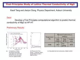
Ph. D. Dissertation Proposal. First Principles Study of Metal-Oxide Interfaces. Hong Zhu Department of Chemical, Materials & Biomolecular Engineering Institute of Materials Science, University of Connecticut Major Advisor: Prof. Rampi Ramprasad Associate Advisor: Prof. Harold Brody

E N D
Ph. D. Dissertation Proposal First Principles Study of Metal-Oxide Interfaces Hong Zhu Department of Chemical, Materials & Biomolecular Engineering Institute of Materials Science, University of Connecticut Major Advisor: Prof. RampiRamprasad Associate Advisor: Prof. Harold Brody Associate Advisor: Prof. Rainer Hebert
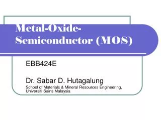
Motivation: MOS devices Vt Gate electrode (poly-Si) I Insulating layer (SiO2) - - - - - - - - - - - - - - - - - - - - - - source drain Si substrate (p-type)
Poly Si electrode 1.1nm SiO2 Silicon substrate Motivation: MOS miniaturization Poly-Si metal source drain Poly-Si SiO2 source drain SiO2 HfO2 source drain Si substrate Si substrate Si substrate Si substrate b a Metal Metal • Stability(1000 0C) • Effective work function (EWF) • Intel 65nm production: 2005 • SiO2 only 3-4 atomic layers thick. • Intel 45nm production: 2007 • metal gate & HfO2 based high k.
Motivation: Effective work function (EWF) Evac,o Evac,m CBM EWF WF EF Di,net VBM Metal HfO2 EWF=WF+4πDi,net/A NMOS: ~4 eV PMOS: ~5.1 eV
Motivation: Metal gate issues Metal After high T annealing • EWF thermal instability • Large Vt • Interesting EWF shifts due to interfacial doping layer. • H.Y. Yu, et al, IEEE Electron Device Lett. 25, 337 (2004). • W. S. Hwang et al, IEEE T ELECTRON DEV 55, 2469 (2008) • S. B. Samavedam et al, Electron Devices Meeting (2003). 4. W. S. Yang, et al, Surface and coating tech. 131, 79 (2000). 5. H.-C. Wen, (2006), unpublished Ph.D.thesis, The University of Texas at Austin.
Outline • Objectives • EWF thermal instabilities • Critical factors of dopants on EWF shifts • Feasibilities of various approaches to tune EWFs • Completed research • WFs of Pt, TiCxN1-x and TaCxN1-x • Interface phase diagrams for Pt-HfO2 • EWF as a function of interfacial structure, T and PO2 • Summary • Future research • Tuning Di,net (or EWF) by adding doping layer (DL) or molecular nanolayer (MNL) at metal-HfO2 interfaces
Vacuum work functions The stacking sequence Ti/Ta C/N
Vacuum work function Pure TiC Pure TiN (a) Pt (b) TiCxN1-x
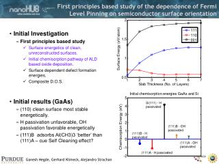
Vacuum work function exp. (111) Pt: 5.8~5.9 eV exp. (001) TiN: 2.9 eV Pure TiC Pure TiN (a) Pt (b) TiCxN1-x Surface orientation controls the work function significantly. • Y. Saito et al, Appl. Surf. Sci. 146, 177 (1999). • R. Martin, Electronic Structure: Basic Theory and Practical Methods (Cambridge University Press, New York, 2004).
Interfacephasediagram Hf O Abrupt interface (ɵO=1ML) Pt First principles thermodynamics Oxidized interface (ɵO=2ML) Clean interface (ɵO=0ML)
Interfacephasediagram W.-B. Zhang, and B.-Y. Tang, Appl. Phys. Lett. 94, 091901 (2009). W.-X. Li, C. Stampfl, and M. Scheffler, Phys. Rev. B 68, 165412 (2003).
Interfacephasediagram: Si-HfO2 : SiO2 : decomposed interface : critical condition for SiO2 to decompose S.J. Wang, et al, Appl. Phys. Lett. 82, 2047 (2003) M. Copel, et al, Appl. Phys. Lett. 85, 458 (2004). N. Miyata, et al, Appl. Phys. Lett. 82, 3880 (2003).
EWF of Pt-HfO2 as a function of θO EWF=WF+4πDi,net/A Di,net (or EWF) is dependent on θO.
Thermal instability of EWF Averaged EWF: Achievable range The interfacial O coverage variation with T and P is responsible for EWF instability. The reported experimental values: 4.6-5.51 eV
Outline • Objectives • EWF thermal instabilities • Critical factors of dopants on EWF shifts • Feasibilities of various approaches to tune EWFs • Completed research • Vacuum WFs of Pt, TiCxN1-x and TaCxN1-x • Interface phase diagrams for Pt-HfO2 • EWF as a function of interfacial structure, T and PO2 • Summary • Future research • Tuning Di,net (or EWF) by adding doping layer (DL) or molecular nanolayer (MNL) at metal-HfO2 interfaces
Summary • Methodology: • Study vacuum WF for multicomponent system • Create the interface phase diagrams • Compute EWF & investigate (T,P) dependence of EWF • Issues addressed • Identify factors that control the vacuum WFs of several metals • Investigate the structure for two important interfaces • Illustrate the importance of O point defects on EWFs.
Outline • Objectives • EWF thermal instabilities • Critical factors of dopants on EWF shifts • Feasibilities of various approaches to tune EWFs • Completed research • Vacuum WFs of Pt, TiCxN1-x and TaCxN1-x • Interface phase diagrams for Pt-HfO2 • EWF as a function of interfacial structure, T and PO2 • Summary • Future research • Tuning Di,net (or EWF) by adding doping layer (DL) or molecular nanolayer (MNL) at metal-HfO2 interfaces
Future research After high T annealing Metal (Pt, TiN) DL HfO2 Doping Layer (DL): Al2O3, La2O3, Y2O3 • H.Y. Yu, et al, IEEE Electron Device Lett. 25, 337 (2004). • W. S. Hwang et al, IEEE T ELECTRON DEV 55, 2469 (2008) • H.-C. Wen, (2006), unpublished Ph.D.thesis, The University of Texas at Austin.
Future research WF for clean Au surface MNL At high T Au S H C H Au Pt Cu/MNL/SiO2 Cu/pre-anneal MNL/SiO2 Cu/SiO2 MNL Molecular nanolayer (MNL): -CH2- molecular chain terminated with S, Hf HfO2 • D. D. Gandhi, et al, nature 477, 299 (2007). • V. De Renzi et al, Phys. Rev. Lett. 95, 046804 (2005) (CH3S)2 (10-6torr)
Acknowledgment Committee members: Profs. RampiRamprasad, Harold Brody and Rainer Hebert Profs. Leon Shaw and Prof. Pamir Alpay Group members: Ning, Tang, Tom, Ghanshyam, Satyesh, Chenchenand Yenny Computational resources: IMS computation clusters; SGI supercomputer in SoE; NSF Teragrid computers Funding: NSF & ACS-PRF
Thank you for your attention! Questions
Computational Methods (a) (b) DFT Exp. (b) • Density Functional Theory (DFT) • Many nuclei-many electron problem one electron problem • Supercell approach • Phase, structure and electronic information • Computational times • Interface calculation 21 days in one AMD 2.0 GHz processor (Supercell of ~120 atoms). • Computational accuracy Experiment (eV) Lattice constant or bond length (angstrom) Theory (eV)
Back up data Interfacial structure plays a major role in determing EWF. The location of Ef and interface defect states affect the charge transfer and the EWF.
Application and Results: TiCxN1-x WF tunability The stacking sequence of TiCxN1-x Slab A Slab B TiC0.5N0.5-terminated TiN-terminated <001> TiC0.5N0.5 TiN TiC0.5N0.5 TiN . . . . . . . . . . . . . . . . . . TiC0.5N0.5 TiN TiN TiC0.5N0.5
TiCxN1-x surface stability (a) TiN(b) TiC0.25N0.75(c) TiC0.5N0.5 (d)TiC0.75N0.25 (e) TiC (111)N-terminated (001)TiC0.5N0.5 -terminated (001)TiN-terminated Shifting with T and PN2 (001)TiN-terminated μN (eV) (001)TiC0.5N0.5 (111)Ti -terminated (111)Ti (111)Ti-terminated -terminated -terminated (001)TiC0.5N0.5 -terminated The (001) surfaces of TiCxN1-x are the most stable surfaces. (111)Ti (001)TiC -terminated -terminated (001)TiC -terminated (111)Ti -terminated
Importance of EWF Band diagram across Si/HfO2/ideal metal gate stack: (a) NMOS, (b) PMOS. Threshold voltage (Vt) is ~ 0. WF and EWF are EF with respect to metal vacuum level and oxide vacuum level, respectively.
MOS capacitor- flat band • The voltage separating the accumulation and depletion regime is referred to as the flatband voltage, VFB. • The flatband voltage is obtained when the applied gate voltage equals the workfunction difference between the gate metal and the semiconductor. • If there is a fixed charge in the oxide and/or at the oxide-silicon interface, the expression for the flatband voltage must be modified accordingly.
High k issues • High leakage currents and low dielectric constant due to crystallization • As-deposited: amorphous (preferred) • Crystallizes at 400~500 °C • Doped HfO2 with alloying elements. • Si, Y, La, F, N • Increase crystallization temperatures • Stabilize higher k phases amorphous cubic tetragonal monoclinic k ~ 30 k ~ 29 k ~ 35 k ~ 16
Si-ѲO-m-HfO2: Interface phase diagram : SiO2 : critical condition for SiO2 to decompose :decomposed interface S. J. Wang, et al., Appl. Phys. Lett. 85, 2047 (2003) M. Copel, et al., Appl. Phys. Lett. 85, 458 (2004). N. Miyata, et al., Appl. Phys. Lett. 82, 3880 (2003).