Download
1 / 47
480 likes | 634 Views
CSR calculation by paraxial approximation. Tomonori Agoh (KEK). Seminar at Stanford Linear Accelerator Center, March 3, 2006. Introduction. Short Bunch. Colliders — for high luminosity ERL — for short duration light FEL — for high peak current.

E N D
CSR calculationby paraxial approximation Tomonori Agoh (KEK) Seminar at Stanford Linear Accelerator Center, March 3, 2006
Introduction Short Bunch • Colliders — for high luminosity • ERL — for short duration light • FEL — for high peak current Also high current may be required for their performance. Future projects of KEK • SuperKEKB (e+e- storage ring collider) N~1x10¹¹ • ERL (Energy Recovery Linac) N~5x10⁸
Coherent Synchrotron Radiation (CSR) High frequency Incoherent Low frequency Coherent In storage rings – Bunch lengthening, Microwave instability, CSR burst Topics • Introduction • Our approach to calculate CSR • Longitudinal instability due to CSR in SuperKEKB positron ring
Tracking length Tracking length Analytic solution (steady, parallel plates) Analytic solution (steady, free space) Shielding & Transient effect • Shielding effect : size of vacuum chamber = h shielding condition : • Transient effect : length of bending magnet = Lm steady condition : Neglect both shielding and transient effect Consider only shielding effect (= neglect transient effect)
Consider only transient effect (= neglect shielding effect) Consider pipe-shaped chamber (= neglect side walls of chamber) When we calculate CSR in a storage ring, we must consider both the vacuum pipe and the magnet length.
Notation coordinate system symbols
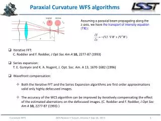
CSR calculation by paraxial approximation Mesh calculation of EM field (E,B) in a beam pipe Assumptions (a) Pipe size a is much smaller than the bending radius of the magnet. (b) Relativistic electrons : (c) Neglect backward waves (paraxial approximation) Surface of the pipe must be smooth (d) Bunch distribution does not change by CSR. Predictable change can be considered. The dynamic variation of the bunch can be considered with particle tracking. G.V.Stupakov, I.A.Kotelnikov, PRST-AB, 6, 034401 (2003) “Shielding and synchrotron radiation in toroidal waveguide”
Time domain : Frequency domain : (5) Inverse Fourier transform Back to the time domain Calculation procedure • Begin with Maxwell equations (E, B) in accelerator coordinates (x,y,z;s) ( We do not handle the retarded potential (A,Φ).) (2) Fourier transform EM field w.r.t z (3) Approximate these equations Paraxial approximation (4) Solve them by finite difference Beam pipe = boundary condition
Fourier transform • Definition Basis Plane waves propagating forward at the speed of light • Field evolution • Fourier transform of the derivatives Differentiation with respect to s acts not only on the basis: exp(ik(s-t)) but also on the field: f(k,s) becausewe consider the field evolution.
Gauss’s low: (1) Fourier transform eq.(1) to the frequency domain, neglect small terms Magnetic field Lorentz force All field components are given by the transverse E-field: Ex and Ey.
Fundamental equation From Maxwell equations, (2) Horizontal direction Vertical direction (3) where (4) Fourier transform of Eq.(2) is given by (5)
Neglect higher order terms (6) where (7) (8) Cx and Cy come from the change of curvature at the edge of bending magnet. Compare first term in Cx, Cy with second term in eq.(6) small
Assuming that s-dependence of the field is weak, neglect the term of 2nd derivative with respect to s: Equation to describe CSR Equation of Evolution • First derivative with respect to s Field evolution (transient behavior) along the beam line • We can solve it numerically step by step with respect to s. • Ex and Ey are decoupled. • If the boundary is a rectangular pipe, i.e., chamber walls are always parallel or perpendicular to the orbit plane, Ex and Ey can be independently calculated.
Usually, mesh size must be in EM field analysis. Our method ignores 2nd derivative, backward waves are ignored. The field consists of only forward waves. Equation of evolution We can factor the plane waves out of the EM field via Fourier transform. We handle only which slowly changes along the beam line. Mesh size can be larger than the actual field wavelength. The term of 1st derivative w.r.t. s describes the evolution of the field.
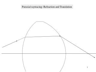
What is paraxial approximation ? Originally, the paraxial approximation is a technique for LASER analysis. Consider a laser beam propagating in a crystal whose index of refraction is not uniform. Laser beam has strong directivity also in the crystal, however, laser is no longer the plane wave in it. From Maxwell equations in the cristal with Cartesian coordinates, (3) Laser is not a plane wave in the crystal but still similar to plane wave. Paraxial ray Eq.(3) becomes A ray propagating almost parallel to the optical axis Neglect the term of second derivative with respect to z,
Equation of laser in a crystal Laser is bent because of the non-uniform medium. (4) LASER n = index of refraction of the crystal optical axis • Equation of evolution without source term (in crystal) (5) Index of refraction of the bending magnet (in bending magnet) Eq.(5) says that light is bent in vacuum. optical axis Our optical axis is curved. radiation
The assumption is the condition so that the radiation field can be a paraxial ray. Role of beam pipe Beam pipe is necessary in our approach. The light, emitted from a bunch, cannot deviate from the s-axis due to the reflection on the pipe wall. The radiation always propagates near around the axis. Paraxial approximation works because of the beam pipe.
Schrödinger equation Klein-Gordon equation (m = rest mass) In the nonrelativistic limit: Factor the plane wave out of the wave function, deal only with the rest part Neglect the term of 2nd derivative w.r.t. time, Equation of evolution without source term — Schrödinger equation —
Scale length of Field Equation of evolution without source term Normalize x, y, s with dimensionless variables The equation becomes put { }=1 Typical scale length of the field transverse longitudinal Mesh size to resolve the field transverse 1/5 ~ 1/10 is enough. longitudinal
Examples to which this approach cannot be applied • Free space or very large vacuum chamber • EM field is no longer a paraxial ray. • Chamber structure so that backward waves are produced • Bellows, Cavity Chamber wall must be smooth. • Ultra-short bunch, or fine structure in the bunch • Fine mesh is required to resolve the field. (expensive) • The shortest bunch length I computed is 10 microns in 6cm pipe. • Bunch profile with sharp edge,e.g. rectangular, triangular, etc • Bunch profile must be smooth.
Flexibility of this approach • Bending radius does not have to be a constant but can be a function of s. Varying the radius Arbitrary smooth beam line can be simulated. • One can consider fringe field of magnet if needed. • Calculation can be performed also in the drift space. • CSR in wigglers • Chamber cross section does not have to be uniform along the beam line if the chamber does not produce backward waves. • Consider a vacuum chamber whose cross section gradually varies along the beam line, one can obtain the EM field. • Collimator impedance • Predictable change of bunch profile such as bunch compressor • Electrons of a finite energy
G.V.Stupakov, I.A.Kotelnikov, PRST-AB, 6, 034401 (2003) “Shielding and synchrotron radiation in toroidal waveguide” Eigenvalue problem Spectrum is discrete because of the eigenmodes. T.Agoh, K.Yokoya, PRST-AB, 7, 054403 (2004) Equation of evolution Initial value problem Continuous spectrum
Finite energy Maxwell equations with a finite energy in the frequency domain Ignoring small terms, which has an error: (e.g.) bunch length chamber radius energy Relative error
Algorithm Solve equation of evolution with boundary condition Discretize the equation by central difference: Solve initial condition at the entrance of bending magnet (radius=∞) Proceed field evolution step by step along s-axis
Comparison of steady CSR Longitudinal E-field between parallel plates Longitudinal E-field in free space chamber size: w=34cm, h=28cm chamber width: w=50cm
CSR in a steady state Equation of evolution in a steady state Assuming free space, the exact solution can be obtained analytically Considering infinite parallel plates, we can solve it. Also this impedance can be obtained by taking a limit in equation: n infinity circular motion R. Warnock, SLAC-PUB-5375 (1990)
Transient CSR in free space E.L.Saldin, E.A.Schneidmiller, M.V.Yurkov, Nucl.Inst.Meth. A398, p373 (1997)
Low frequency limit ⇒ Resistive wall impedance : High frequency limit ⇒ Steady CSR in free space : Impedance of CSR & Resistive wall Longitudinal impedance in a copper pipe (10cm square, R=10m, Lmag=1m) Real part Imaginary part
CSR in the drift space CSR goes out a bend and propagates in the drift space, where particles are still affected with CSR. at exit of bend at 9m from exit at 3m from exit 1. Longitudinal delay because of reflection 2. Sinusoidal behavior as it propagates Real part Imaginary part
Error of parallel plates model Chamber size (full width × full height) • Square pipe : 94 ×94 mm2 (solid line) • Parallel plates : 400 ×94 mm2 (dashed line) Bunch length : Model error Δ= 8.8% Model error Δ=46% Parallel plates model may work for very short bunch but we should consider a beam pipe for storage rings.
Transverse force of CSR Vertical force Fy Horizontal force Fx neglected Ya.S.Derbenev, V.D.Shiltsev, SLAC-PUB-7181 (1996) “Transverse effects of Microbunch Radiative Interaction”
Horizontal force on a curved trajectory Horizontal force consists of not only forward waves but also backward waves. G.Geloni, E.Saldin, E.Schneidmiller, M.Yurkov, DESY 03-165 (2003) my result forward backward Since CSR is emitted forward, the backward component in Fx is not the radiation but a kind of space charge force. “centrifugal space charge force”, “Talman force” We neglect backward waves in the paraxial approximation, the horizontal force may be incorrect in our approach.
CSR in SuperKEKB KEKB factory (e+e- storage ring collider) Upgrade plan to SuperKEKB (2009) L=4x1035 We will keep using present magnets to save money and R&D time. Bending radius LER (positron): R=16.31mHER (electron): R=104.5m Positron bunch will be affected with CSR.
CSR in SuperKEKB Energy change due to CSR (Longitudinal wakefield for a single bend) smaller chamber Small chambers suppress CSR. KEKB SuperKEKB CSR effect is 14 times larger We will make new vacuum chamber to suppress electron cloud effect.
Variation of bunch profile In a storage ring, bunch distribution changes by wakefield and damping. CSR depends on the longitudinal bunch shape, we must consider the variation of bunch shape Initial distribution (macro-particles) Green function of CSR (thin Gaussian distribution) Initial distribution (macro-particles histogram) Field calculation (superposition) Equation of motion bins replaced by Green function iteration New charge distribution Macro-particle tracking
Microwave instability due to CSR Equations of longitudinal motion resistive pipe considered Resistive wall wakein the drift space • 134 arc bends are considered for CSR. • Wiggler is neglected (should be considered). • Wiggler is taken into account in rad. damping. • Copper pipe of square cross section • (Actual chamber is a round pipe) • Option: Resistive wall wake in the drift space
Chamber half size: r=47mm (only CSR) Charge distribution Energy distribution
(only CSR) Chamber half size: r=25mm Charge distribution Energy distribution
Saw-tooth instability Resistive wall wakefield reduces the saw-tooth amplitude. rms energy spread vs number of turns only CSR CSR + RW wake in the drift space
Bunch length, Energy spread vs bunch charge only CSR CSR +RW in drift space
Bunch profile Vacuum chamber size ( only CSR ) back front ( CSR + RW in drift space ) Resistive wall wakefield does not change the instability threshold. Bunch leans forward because of energy loss due to the resistive wall wakefield.
CSR in the drift space CSR in the drift space considered not considered (only in bend) Real part Imaginary part Ib=2mA Threshold current Ith=0.9mA Ith=0.7mA bunch spectrum (sigz=3mm) bunch spectrum (sigz=0.6mm) CSR in the drift space relaxes the longitudinal instability.
Negative momentum compaction(only CSR considered, no RW wake in drift space) Bunch length Energy spread Ith=0.4mA Ith=0.9mA Ib=0.4mA Ib=2mA negative positive negative positive Bunch profile back front
Numerical problem Bunch profile Longitudinal CSR wake particle noise Width of Gaussian Green function
Instability threshold for Green function width Energy spread vs bunch current Threshold vs Green function width Width of Green function Threshold current does not converge for Green function width. We cannot distinguish between instability and particle noise.
Conclusions • CSR calculation is performed by paraxial approximation. • Shielding by a beam pipe, Transient state, Resistive wall • CSR in the drift space • Our approach has a defect in the horizontal space charge force. • backward wave ignored • CSR will induce longitudinal instability in SuperKEKB positron ring. • The threshold bunch current is less than 0.9mA in the present chamber (r=47mm). • Vacuum chamber of r=28mm will suppress the CSR effect. However, the small chamber may cause side effects. • CSR in the drift space relaxes the longitudinal instability. • Particle tracking does not work for microwave instability, threshold current is not clear.