Download
1 / 19
190 likes | 349 Views
Muon Drift Tube Gases. Chris Clark Advisors: Rachel Avramidou, Rob Veenhof. Muon Drift Tubes. Incoming muons ionize gas molecules Electrons produced in ionizations are accelerated toward the anode wire by the electric field. Electron Avalanche.

E N D
Muon Drift Tube Gases Chris Clark Advisors: Rachel Avramidou, Rob Veenhof
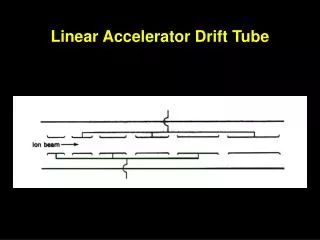
Muon Drift Tubes • Incoming muons ionize gas molecules • Electrons produced in ionizations are accelerated toward the anode wire by the electric field
Electron Avalanche • Fast electrons can cause additional ionizations near wire • Exponential growth of electrons • Repulsive force of many electrons near the wire causes displacement of electrons in the wire
GARFIELD • Simulates passage of a muon through a drift tube and generates the resulting drift-lines of electrons and ions • Produces a distribution of drift times (the time it takes for an electron to reach the wire*) *Actually it takes about 20 electrons due to the discriminator
Simulation Results • We recorded the maximum time from a drift time distribution for electrons that started just inside the tube wall • We did this many times after tweaking the temperature, pressure, or CO2 fraction of the gas and found linear fits for the drift times.
Conclusions • The slopes of the linear fits were farther from the experimental values than previous simulations • We ran all the simulations again with 10x higher statistics and the slopes were only slightly affected • Possibly this means that the experiments are not controlled tightly enough
Penning Ionization • Penning Ionization occurs when an excited moleculeionizes another molecule by collision • In this section I will explain the ideas behind a simple equation that I developed to predict the probability of Penning ionization
Definition • Onlysome excited states actually have enough potential energy to ionize another gas species • We define the probability of Penning ionization to be the fraction of the energy in the molecules in these excited states that will eventually end up causing ionization by the Penning process • We use the terms ‘energy’ and ‘eventually’ so that the energy can be transferred to another molecule before Penning ionization
Sample Gases • We used the gas that will be found in the ATLAS muon drift tubes: 93% Argon, 7% CO2 • Another gas with good information already available is the gas in ALICE: 90% Neon, 10% CO2 • For both of these gases there is only one type of Penning ionization: Ar*+CO2 and Ne*+CO2
Energy Destinations • A good way to understand the problem is to look at where the energy can end up in a stable form (excited states will deexcite) • Conceivable options are: • Ionization of CO2 • Kinetic Energy • Escape from the system
Photon Deexcitation • Natural Radiative Lifetime of Argon in the D-Level excited state is probably around 3.7 ns (given by inverse of Transition Probability or Einstein A Coefficient) • The mean free time of an Argon atom in this gas is about 1.5 ns • Somewhere around 1/3 of excited Argon atoms will deexcite before undergoing any collisions
Photon Deexcitation • A photon sees roughly the same cross sections as an excited Argon atom because the cross sections are primarily determined by the target • The photons won’t escape the system because of their short mean free paths and because the walls of the tube are Aluminum, which is very reflective • Can pretend that photon deexcitation never happens and it won’t affect the Penning ionization probability
Concerns • Kinetic-Assisted Ionization – If a lower energy excited state had enough kinetic energy it could still cause ionization, but this will never happen at our temperatures • Associative Ionization – If two excited molecules collide then their combined excitation energy can cause an ionization, but this type of collision seems less probable
Collisions of the 2nd Kind • Inelastic collisions of the second kind are collisions in which the excitation energy of one molecule is released and ends up in the kinetic energy of the other molecule • After such a collision ionization will probably not happen because it is thermodynamically unfavored • Together with inelastic collisions of the first kind, these collisions are responsible for maintaining the relation specified by the Boltzmann factor
Summary • The energy from the D-Level excited states can only end up as Penning ionization or kinetic energy • Penning ionization only occurs if an excited Argon atoms collides with a CO2 • Inelastic Collisions of the second kind are relegated to occurring upon collision with another Argon atom • No energy escapes and these are the only significant processes
Penning Ionization Probability • Here, f is the fraction of CO2, σPenning is the cross section for Penning ionization, and σInelastic is the cross section for inelastic collisions of the second kind • σInelastic is approximated by the van der Waals radius of Argon • σPenning is taken from experimental values, which are hard to find
Empirical Comparison *This is so theoretical there are no significant figures! **The Penning cross section for Ne*+CO2 was used here ***This value was produced by Rob Veenhof using a more sophisticated method that yields a range values
Conclusion • The equation for Penning ionization probability is not ready to be used as a tool – it needs further testing, further consideration of some factors, and more precise cross section measurements • However, with the ideas in place, hopefully the hard part is over
Funding Sources: University of Michigan National Science Foundation Ford Motor Company Help Sources: Rachel Avramidou Rob Veenhof Peter Cwetanski Adrian Fabich Homer Neal Jean Krisch Jeremy Herr Acknowledgements