Download
1 / 39
390 likes | 684 Views
Learn about common electrical symbols used in automotive wiring diagrams including connectors, grounds, and components. Understand the representations of wires, switches, relays, and more to troubleshoot vehicle electrical systems effectively.

E N D
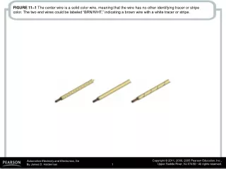
FIGURE 11–1 The center wire is a solid color wire, meaning that the wire has no other identifying tracer or stripe color. The two end wires could be labeled “BRN/WHT,” indicating a brown wire with a white tracer or stripe.
FIGURE 11–2 Typical section of a wiring diagram. Notice that the wire color changes at connection C210. The “.8” represents the metric wire size in square millimeters.
FIGURE 11–3 Typical electrical and electronic symbols used in automotive wiring and circuit diagrams.
FIGURE 11–4 In this typical connector, note that the positive terminal is usually a female connector.
FIGURE 11–5 The symbol for a battery. The positive plate of a battery is represented by the longer line and the negative plate by the shorter line. The voltage of the battery is usually stated next to the symbol.
FIGURE 11–6 The ground symbol on the left represents earth ground. The ground symbol on the right represents a chassis ground.
FIGURE 11–7 Starting at the top, the wire from the ignition switch is attached to terminal B of connector C2, the wire is 0.5 mm 2 (20 gauge AWG), and is yellow. The circuit number is 5. The wire enters connector C202 at terminal B3.
FIGURE 11–8 The electrical terminals are usually labeled with a letter.
FIGURE 11–9 Two wires that cross at the dot indicate that the two are electrically connected.
FIGURE 11–10 Wires that cross, but do not electrically contact each other, are shown with one wire bridging over the other.
FIGURE 11–11 Connectors (C), grounds (G), and splices (S) are followed by a number, generally indicating the location in the vehicle. For example, G209 is a ground connection located under the dash.
FIGURE 11–12 The ground for the battery is labeled G305 indicating the ground connector is located in the passenger compartment of the vehicle. The ground wire is black (BLK), the circuit number is 50, and the wire is 32 mm2 (2 gauge AWG).
FIGURE 11–13 The symbol for light bulbs shows the filament inside a circle, which represents the glass ampoule of the bulb.
FIGURE 11–14 An electric motor symbol shows a circle with the letter M in the center and two black sections that represent the brushes of the motor. This symbol is used even though the motor is a brushless design.
FIGURE 11–15 Resistor symbols vary depending on the type of resistor.
FIGURE 11–16 A rheostat uses only two wires—one is connected to a voltage source and the other is attached to the movable arm.
FIGURE 11–17 Symbols used to represent capacitors. If one of the lines is curved, this indicates that the capacitor being used has a polarity, while the one without a curved line can be installed in the circuit without concern about polarity.
FIGURE 11–18 The gridlike symbol represents an electrically heated element.
FIGURE 11–19 A dashed outline represents a portion (part) of a component.
FIGURE 11–21 This symbol represents a component that is case grounded.
FIGURE 11–22 (a) A symbol for a single-pole, single-throw (SPST) switch. This type of switch is normally open (N.O.) because nothing is connected to the terminal that the switch is contacting in its normal position. (b) A single-pole, double-throw (SPDT) switch has three terminals. (c) A double-pole, single-throw (DPST) switch has two positions (off and on) and can control two separate circuits. (d) A double-pole, double-throw (DPDT) switch has six terminals—three for each pole. Note: Both (c) and (d) also show a dotted line between the two arms indicating that they are mechanically connected, called a “ganged switch”.
FIGURE 11–23 (a) A symbol for a normally open (N.O.) momentary switch. (b) A symbol for a normally closed (N.C.) momentary switch.
FIGURE 11–24 Using a marker and color-coding the various parts of the circuit makes the circuit easier to understand and helps diagnosing electrical problems easier. (Courtesy of Jorge Menchu.)
FIGURE 11–25 A relay uses a movable arm to complete a circuit whenever there is a power at terminal 86 and a ground at terminal 85. A typical relay only requires about 1/10 ampere through the relay coil. The movable arm then closes the contacts (#30 to #87) and can relay 30 amperes or more.
FIGURE 11–26 A cross-sectional view of a typical fourterminal relay. Current flowing through the coil (terminals 86 and 85) causes the movable arm (called the armature) to be drawn toward the coil magnet. The contact points complete the electrical circuit connected to terminals 30 and 87.
FIGURE 11–27 A typical relay showing the schematic of the wiring in the relay.
FIGURE 11–28 All schematics are shown in their normal, nonenergized position.
FIGURE 11–29 A typical horn circuit. Note that the relay contacts supply the heavy current to operate the horn when the horn switch simply completes a low-current circuit to ground, causing the relay contacts to close.
FIGURE 11–30 When the relay or solenoid coil current is turned off, the stored energy in the coil flows through the clamping diode and effectively reduces voltage spike.
FIGURE 11–31 A resistor used in parallel with the coil windings is a common spike reduction method used in many relays.
FIGURE 11–32 A typical wiring diagram showing multiple switches and bulbs powered by one fuse.
FIGURE 11–33 To add additional lighting, simply tap into an existing light wire and connect a relay. Whenever the existing light is turned on, the coil of the relay is energized. The arm of the relay then connects power from another circuit (fuse) to the auxiliary lights without overloading the existing light circuit.
FIGURE 11–34 Always check the simple things first. Check the fuse for the circuit you are testing. Maybe a fault in another circuit controlled by the same fuse could have caused the fuse to blow. Use a test light to check that both sides of the fuse have voltage.
FIGURE 11–35 (a) After removing the blown fuse, a pulsing circuit breaker is connected to the terminals of the fuse. (b) The circuit breaker causes current to flow, then stop, then flow again, through the circuit up to the point of the short-to-ground. By observing the Gauss gauge, the location of the short is indicated near where the needle stops moving due to the magnetic field created by the flow of current through the wire.
FIGURE 11–36 A Gauss gauge can be used to determine the location of a short circuit even behind a metal panel.
FIGURE 11–37 A tone generator-type tester used to locate open circuits and circuits that are shorted-to-ground. Included with this tester is a transmitter (tone generator), receiver probe, and headphones for use in noisy shops.
FIGURE 11–38 To check for a short-to-ground using a tone generator, connect the black transmitter lead to a good chassis ground and the red lead to the load side of the fuse terminal. Turn the transmitter on and check for tone signal with the receiver. Using a wiring diagram, follow the strongest signal to the location of the short-to-ground. There will be no signal beyond the fault, either a short-to-ground as shown or an open circuit.
FIGURE 11–39 Antistatic spray can be used by customers to prevent being shocked when they touch a metal object like the door handle.