
Thermo 49i
E N D
Presentation Transcript
The main part of quality control for the Thermo 49i ozone analyzer is to supply known concentrations of ozone (cal gas) from the API 401x ozone calibrator to the 49i Thermo analyzer at least once every other week. When the system is set up there will be tubing that runs from the API calibrator, through the tubing support structure to a tee at the sample inlet. The tee is also connected to the Thermo ozone analyzer sample tubing. When not doing a calibration check, outside air passes through the tee and is directed to the inlet of the 49i ozone analyzer for normal ozone measurement. To be sure we don’t draw inside air to the sample inlet we place a valve in the tubing near the calibrator to isolate the inlet tee from inside. When checking the calibration the ozone calibrator is first turned on and allowed to warm for at least an hour. During this warm up period, the calibrator output gas is sent through the vent connection on the calibrator to the outside. This vent gas is never used – it is just exhausted out of the workspace. It must be vented or the internal photometer will be pressurized since it draws air from the calibrator output manifold. When checking the calibration we open the valve placed in the tubing that goes between the calibrator and the sample inlet tee. Then, we close the vent so all the calibration gas is sent to the inlet. In that configuration the cal gas will vent through the sample inlet tubing stub and also be drawn to the Thermo ozone analyzer just as if it was sampling outside air. This tests the entire sample collection system, as well as the Thermo ozone analyzer. See the next slide for an illustration I put together to show the system.
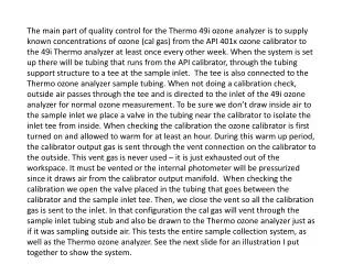
When stopcock (valve 1) is open, the calibration gas of known concentration goes through the calibration tubing and connects to the tee at the sample inlet. It vents through the inlet and also enters the 49i ozone analyzer’s sample tubing. To ensure sufficient venting at the inlet and avoid outside air mixing with the calibration gas at the inlet, we close the vent at the calibrator (Valve 2) and provide a total flow through the calibrator of approximately 4 liters per minute. Cal gas Cal Gas After the calibrator is warmed, to check the analyzer open valve 1 and then close valve 2. When finished, open valve 2 and then close valve 1 Cal Gas Vent Closed stopcock Valve (1) Outside Sample air Sample air when valve 1 is closed, or cal gas when valve 1 is open Open stopcock Valve (2) Ozone Sample tubing (¼ inch FEP Teflon tubing) Calibrator ozone out tubing (¼ inch FEP Teflon tubing) Flow is out Calibrator vent line (¼ inch Tubing) Flow is in NOTE: Calibration gas MUST pass through the 49i sample filter. The filter can only be changed after the check Thermo 49i API 401x Ozone calibrator (set to 4 liters per minute total flow) Ozone analyzer