Download
1 / 64
650 likes | 746 Views
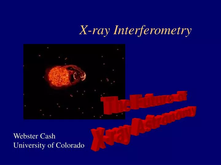
X-ray Interferometry. The Future of X-ray Astronomy. Webster Cash University of Colorado. Co-Investigators. Steve Kahn - Columbia University Mark Schattenburg - MIT David Windt – Columbia University Dennis Gallagher – Ball Aerospace. A Sufficiently Good Image is Like a Visit.

E N D
X-ray Interferometry The Future of X-ray Astronomy Webster CashUniversity of Colorado
Co-Investigators • Steve Kahn - Columbia University • Mark Schattenburg - MIT • David Windt – Columbia University • Dennis Gallagher – Ball Aerospace
A Sufficiently Good Image is Like a Visit Resolution Log (arcsec) Improvement Cavemen 100 -- Galileo 3 1.5 Palomar 1 2 HST 0.1 3 VLBA .001 5 Voyager 10-5 7 X-ray Int. 10-7 9
AGN Accretion DiskSimulation @ 0.1as(Chris Reynolds) Seeing the Strong Field Limit Is Believing
Need Resolution and Signal If we are going to do this, we need to support two basic capabilities: • Signal • Resolution
X-ray Sources Are Super Bright Example: Mass Transfer Binary 1037ergs/s from 109cm object That is ~10,000L from 10-4A = 108 B whereB is the solar brightness in ergs/cm2/s/steradian Brightness is a conserved quantity and is the measure of visibility for a resolved object Note: Optically thin x-ray sources can have very low brightness and are inappropriate targets for interferometry. Same is true in all parts of spectrum!
Status of X-ray Optics • Modest Resolution • 0.5 arcsec telescopes • 0.5 micron microscopes • Severe Scatter Problem • Mid-Frequency Ripple • Extreme Cost • Millions of Dollars Each • Years to Fabricate Need Easier Approach
Classes of X-ray Interferometers Dispersive Elements are Crystals or Gratings Non-Dispersive Elements are Mirrors & Telescopes
Achieving High Resolution Use Interferometry to Bypass Diffraction Limit Michelson Stellar Interferometer R=l/20000D R in Arcsec l in Angstroms D in Meters
D d Creating Fringes Requirements • Path Lengths Nearly Equal • Plate Scale Matched to Detector Pixels • Adequate Stability • Adequate Pointing • Diffraction Limited Optics
Pathlength Tolerance Analysis at Grazing Incidence A1 A2 q A1 & A2 in Phase Here If OPD to be < /10 then q q B2 B1 q C S2 S1 d
Beams Cross Flats Detector A Simple X-ray Interferometer
Beams Cross to Form Fringes Two Plane Wavefronts Cross d L
l=qs (where s is fringe spacing) s q=d/L Wavefront Interference
Beam Combiner • Just use two grazing incidence flats to steer two beams together. • Beats will occur, even if not focused • Fringe is spacing function of beam crossing angle • Grazing Incidence Mirrors Only • Flats OK • No • Partially Silvered Mirrors • Diffraction Gratings • Paraboloids • Windows or Filters • Diffraction Limited Optics OK
Optics Each Mirror Was Adjustable From Outside Vacuum System was covered by thermal shroud
Source, filter and slit Interferometer CCD 16m 100m Stray Light Facility MSFC Used Long Distance To Maximize Fringe Spacing
CCD Image @ 1.25keV 2 Beams Separate 2 Beams Superimposed
Fringes at 1.25keV Profile Across Illuminated Region
Test Chamber at CU Ten Meter Long VacuumChamber for Testing Came on-line early May EUV results good Upgrade to x-ray next
Simulation of Fringes An approximate theoretical fringe pattern for our experimental geometry can be obtained by numerically superimposing a series of partial wave amplitudes, A = j e-i(wt-kxj) where the intensity is obtained from the square of the summed amplitudes. The fringe intensity simulations shown next correspond to a superposition of partial waves with 50% of the flux in the Mg Ka line and 50% in the underlying x-ray continuum; the partial wave analysis also incorporates random phase errors with standard deviations of 0.002, 0.005, and 0.01 wavelengths.
Theoretically Perfect Mirrors A monochromatic 1.24 keV x-ray beam
With Imperfections l6328Å/12 RMS surface figure
Technology Summary • X-ray Interferometers Can be Built • Results Can be Modeled Effectively • Provides Basis for Design of Next Generations of X-ray Interferometers
MAXIMThe Micro Arcsecond X-ray Imaging Mission Webster Cash ColoradoNicholas White Goddard Marshall Joy Marshall PLUS Contributions from the Maxim Team http://maxim.gsfc.nasa.gov
Maxim:A Few Science Goals Target Class Goal Resolve the corona of nearby stars: Are other coronal structures like the solar corona? Resolve the winds of OB stars: What kind of shocks drive the x-ray emission? Resolve pre-main sequence stars: How does coronal activity interact with disk? Image of center of Milky Way: Detect and resolve accretion disk? Detailed images of LMC, SMC, M31: Supernova morphology and star formation in other settings Image jets, outflows and BLR from AGN: Follow jet structure, search for scattered emission from BLR Detailed view of starbursts: Resolve supernovae and outflows Map center of cooling flows in clusters: Resolve star formation regions? Detailed maps of clusters at high redshift: Cluster evolution, cooling flows Image Event Horizons in AGNS: Probe Extreme Gravity Limit
Wedge of Flats Flats Detector Observatory Design Arbitrary Distance D
Observatory Design Multiple Spacings and Rotation Angles Needed Simultaneously to Sample UV Plane
Tolerance Table • Notes: • Angular stability is for individual mirrors relative to target direction. • Only the Angular Knowledge requirement grows tighter with baseline, but this is achieved by a (fixed) 2nm relative position knowledge over a longer baseline. • Absolute positioning remains constant as interferometer grows, but does not get tighter!
Four Difficult Areas • Fabrication of Interferometer • Internal Metrology • Hold Mirrors Flat and In Position • Formation Flying • Hold Detector Craft in Position • Pointing • Hold Interferometer on Target
Maxim “The Black Hole Imager” 0.1as Resolution 10,000cm2 Effective Area 0.4-7.0 keV
Maxim Pathfinder 100as Resolution 100cm2 Effective Area 0.4-2.0keV + 6keV Two Spacecraft Formation Flying at 450km Separation
Angular Resolution 100as Baseline 1.4 meters Collecting Area 100cm2 Field of View 10 mas Bandpass 0.5-2keV + 6keV Pointing 30as Spectral Resolution (E/E) 20 Size Single Launch Orbit High Earth or Drift Away Maxim PathfinderPerformance Requirements
1m Maxim Pathfinder Mission Concept Optics Spacecraft Carries: X-ray Interferometers Finder X-ray Telescopes 2 Visible Light Interferometers Laser Ranging System Size: 2.5x2.5x10m Pitch&Yaw Stability: 3x10⁻⁴ arcsec Pitch&Yaw Knowledge: 3x10⁻⁵ arcsec Roll Stability: 20 arcsec Position Stability: ----- 2.5m 10m Detector Spacecraft Carries: X-ray Detector Array Laser Retro Reflectors Precision Thrusters Size: 1x1x1m Pitch&Yaw Stability: 20 arcsec Roll Stability: 20 arcsec Lateral Stability: 5mm Lateral Knowledge: 50 microns Focal Stability: 10 meters Separation 450km 1m
Prime Interferometer Wolter Telescope Pitch Sensor Yaw Sensor Optics CraftFront View
B A D F E C Visible light wavefront from distant star Solution to Pointing Problem Consider, instead, line F. Mount the visible light interferometer on structures at the ends of line F. They then maintain 1nm precision wrt to guide star that lies perpendicular to F. This defines pointing AND maintains lateral position of convergers. (40pm not needed in D and E after all.) A, B, C, D and E all maintain position relative to F.
Detector • Energy Resolution Necessary for Fringe Inversion • CCD is adequate • To get large field of view use imaging quantum calorimeter