Chapter 4 , Use Case and Statechart Diagrams
400 likes | 617 Views
Chapter 4 , Use Case and Statechart Diagrams. Outline of this Class. Use case diagrams Describe the functional behavior of the system as seen by the user Class diagrams Describe the static structure of the system: Objects, attributes, associations Sequence diagrams

Chapter 4 , Use Case and Statechart Diagrams
E N D
Presentation Transcript
Outline of this Class • Use case diagrams • Describe the functional behavior of the system as seen by the user • Class diagrams • Describe the static structure of the system: Objects, attributes, associations • Sequence diagrams • Describe the dynamic behavior between objects of the system • Statechart diagrams • Describe the dynamic behavior of an individual object • Activity diagrams • Describe the dynamic behavior of a system, in particular the workflow.
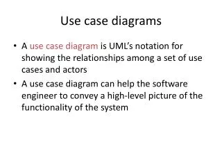
An actor represents a role, that is, a type of user of the system. Passenger PurchaseTicket UML Use Case Diagrams Used during requirements elicitation and analysis to represent external behavior (“visible from the outside of the system”) A use case represents a class of functionality provided by the system. Use case model:The set of all use cases that completely describe the functionality of the system.
Use Case Example Handle Returns Main Success Scenario:A customer arrives at a checkout with items to return. The cashier uses the POS system to record each returned item. Alternate Scenarios: • If they paid by credit, and the reimbursement transaction to their credit account is rejected, inform the customer and play them with cash. • If the item identifier is not found in the system, notify the Cashier and suggest manual entry of the identifier code. • If the system detects failure to communicate with the external accounting system, .....
An actor is a model for an external entity which interacts (communicates) with the system: User External system (Another system) Physical environment (e.g. Weather) An actor has a unique name and an optional description Examples: Passenger: A person in the train GPS satellite: An external system that provides the system with GPS coordinates. Passenger Actors Optional Description Name
• A use case represents a class of functionality provided by the system. • Use cases can be described textually, with a focus on the event flow between actor and system. • The textual use case description consists of 6 parts: Unique name Participating actors Entry conditions Exit conditions Flow of events Special requirements. PurchaseTicket Use Case
1. Name:Purchase ticket 2. Participating actor:Passenger 3. Entry condition: Passenger stands in front of ticket distributor Passenger has sufficient money to purchase ticket 4. Exit condition: Passenger has ticket 5. Flow of events: 1. Passenger selects the number of zones to be traveled 2. Ticket Distributor displays the amount due 3. Passenger inserts money, at least the amount due 4. Ticket Distributor returns change 5. Ticket Distributor issues ticket 6. Special requirements: None. Passenger PurchaseTicket Textual Use Case Description Example
Uses Cases can be related • Extends Relationship • To represent seldom invoked use cases or exceptional functionality • Includes Relationship • To represent functional behavior common to more than one use case.
<<extends>> relationships model exceptional or seldom invoked cases The exceptional event flows are factored out of the main event flow for clarity The direction of an <<extends>> relationship is to the extended use case Use cases representing exceptional flows can extend more than one use case. Passenger PurchaseTicket <<extends>> OutOfOrder TimeOut <<extends>> <<extends>> <<extends>> Cancel NoChange The <<extends>>Relationship
<<includes>> relationship represents common functionality needed in more than one use case. <<includes>> behavior is factored out for reuse, not because it is an exception. The direction of a <<includes>> relationship is to the using use case (unlike the direction of the <<extends>> relationship). Two use cases are related by an include relationship, if one of them includes the second one in its own flow of events. Passenger PurchaseMultiCard PurchaseSingleTicket <<includes>> <<includes>> NoChange Cancel Cancel CollectMoney <<extends>> <<extends>> <<extends>> The <<includes>>Relationship
Student DoHomework Textual Use Case Description Example 1. Name:DoHomework 2. Participating actor:Student 3. Entry condition: • Student received exercise sheet • Student is in good health 4. Exit condition: • Student delivered solution 5. Flow of events: 1. Student fetches the exercise sheet 2. Student reads through the assignments 3. Student processes the assignments and types the solution in his Computer. 4. Student prints out the solution 5. Student delivers the solution in the following exercise 6. Special requirements: None.
Sınıf Çalışması (10 dakika) - Müşteri, garsona sipariş verir. • Restoranda çalışmak isteyen adayların başvurularını restoran yöneticisi değerlendirir. İşe alımları da o yapar. • Restoranda kullanılan malzemeler için düzenli sipariş verilmesi gerekmektedir. Malzemeler belirli bir tedarikçiden sağlanır. • Malzemelerin siparişini restoran yöneticisi verir. Bunu yaparken, sürekli olarak satışları ve stokları takip etmesi gerekir. • Stokları takip etmek için, restoran yöneticisinin tuttuğu düzenli raporlar bulunur.
Order Food Customer Service Person Hire Employee Applicant <<uses>> Reorder supplies Manager Supplier <<uses>> Track sales and inv. data Produce mgt. reports Sınıf Çalışması
Used during analysis To refine use case descriptions to find additional objects (“participating objects”) Used during system design to refine subsystem interfaces Instances are represented by rectangles. Actors by sticky figures Lifelines are represented by dashed lines Messages are represented by arrows Activations are represented by narrow rectangles. TicketMachine Passenger selectZone() insertCoins() TicketMachine pickupChange() zone2price selectZone() insertCoins() pickupChange() pickUpTicket() pickUpTicket() Focus on Controlflow Sequence Diagrams Messages -> Operations on participating Object
ZoneButton TarifSchedule Display Passenger selectZone() lookupPrice(selection) price displayPrice(price) Sequence Diagrams can also model the Flow of Data Dataflow • The source of an arrow indicates the activation which sent the message • Horizontal dashed arrows indicate data flow, for example return results from a message …continued on next slide...
Messages • Define a particular communication between lifelines of an interaction • Examples of communication • raising a signal • invoking an operation • creating or destroying an instance • Specify (implicitly) sender and receiver • are shown as a line from the sender to the receiver • Form of line and arrowhead reflect message properties
Message Types • Asynchronous • Synchronous • Call and Object creation • Reply • Lost • Found
Lifeline and Execution Specification • A lifeline represents an individual participant (or object) in the interaction • A lifeline is shown using a symbol that consists of a rectangle forming its “head” followed by a vertical line (which may be dashed) that represents the lifetime of the participant • An execution specification specifies a behavior or interaction within the lifeline • An execution specification is represented as a thin rectangle on the lifeline.
CoinIdentifier Display CoinDrop Passenger insertChange(coin) lookupCoin(coin) price displayPrice(owedAmount) [owedAmount<0] returnChange(-owedAmount) Sequence Diagrams: Iteration & Condition …continued from previous slide... ChangeProcessor * Iteration • Iteration is denoted by a * preceding the message name • Condition is denoted by boolean expression in [ ] before the message name Condition …continued on next slide...
Passenger createTicket(selection) Ticket print() free() Creation and destruction …continued from previous slide... Creation of Ticket ChangeProcessor Destruction of Ticket • Creation is denoted by a message arrow pointing to the object • Destruction is denoted by an X mark at the end of the destruction activation • In garbage collection environments, destruction can be used to denote the end of the useful life of an object.
Sequence diagram: An Example Lifeline ExecutionSpecification Message Sequence diagrams represent the behavior of a system as messages (“interactions”) between different objects.
Sequence Diagram Properties • UML sequence diagram represent behavior in terms of interactions • Useful to identify or find missing objects • Time consuming to build, but worth the investment • Complement the class diagrams (which represent structure).
Sınıf Çalışması (15 dakika) Müşterinin ATM’den para çekmek istemesine ait sıralama (sequence) diyagramını çiziniz. • Sokulan kart kontrol edilmeli. • Eğer onaylanırsa, müşterinin istediği miktar kontrol edilmeli. • Eğer onaylanırsa, işlem başlatılmalı. • Para verildikten sonra, müşteriye dekont verilmesi. • Müşteri hesabında yapılan işlemlerin kaydedilmesi.
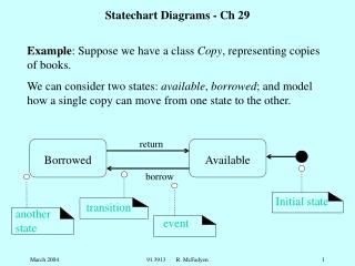
Increment Hours button2Pressed button1&2Pressed Blink Hours button1Pressed Increment Minutes button2Pressed button1&2Pressed Blink Minutes button1Pressed Increment Seconds button2Pressed Blink Stop Seconds Blinking UML first pass: Statechart diagrams Initial state Event Transition State Final state Represent behavior of a single object with interesting dynamic behavior.
How to draw statechart diagrams? • Identify important objects to be analyzed. • Identify the states. • Identify the events.
UML Summary • UML provides a wide variety of notations for representing many aspects of software development • Powerful, but complex • UML is a programming language • Can be misused to generate unreadable models • Can be misunderstood when using too many exotic features • We concentrated on a few notations: • Functional model: Use case diagram • Object model: class diagram • Dynamic model: sequence diagrams, statechart and activity diagrams