Download
1 / 64
760 likes | 1.06k Views
Adaptive Optics: basic concepts, principles and applications Short course of lectures. Vadim Parfenov Res.Ctr. “S.I.Vavilov State Optical Institute” 14, Birzhevaya linia, St.Petersburg, 199034, Russia vadim@optilas.spb.ru.

E N D
Adaptive Optics:basic concepts, principles and applicationsShort course of lectures Vadim Parfenov Res.Ctr. “S.I.Vavilov State Optical Institute” 14, Birzhevaya linia, St.Petersburg, 199034, Russia vadim@optilas.spb.ru
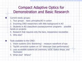
Lecture #2 Applications of Adaptive Optics.New technologies.Future of AO
Adaptive optics technology AO technology deals with real-time correction of optical aberrations. Used mainly in research environment. Established applications: - Astronomy; - Military optical systems; -Laser technology; - Ophthalmology.
Optical observations by ground-based astronomers have long been limited by the distorting effects of the Earth’s atmosphere. Primary mirrors of telescopes have been polished to exquisite accuracy for telescopes with apertures as large as 10 meters, but at optical wavelengths these can deliver an angular resolution typically no better than of a 25-cm telescope, as atmospheric turbulence deforms the image on a millisecond time scale. Two possible solutions of the problem:1.Space Telescopes (Extremely expensive !);2. Adaptive OpticsSystems which measure and undo the effects of clear-air turbulence in real time.
I.Existing and funded ProjectsSome examples of adaptive optics systems currently working for astronomy: -ESO-France-Come-On-Plus system at La Silla Observatory, Chile (52 actuators on a 3.6-m telescope) (this is improved version of an early prototype called Come-On) (19 actuators on the ESO 3.6-m telescope)); - the University of Hawaii system at the Canada-France-Hawaii Telescope (CFHT) on Mauna Kea, Hawaii, USA (12 actuators on a 3.6-m telescope); - two 10-m Keck telescopes, Mauna Kea, Hawaii, USA (primary mirror consists of 36 hexagonal elements); - 8.5-m Gemini North telescope product of a collaboration of the U.S.A., Canada, the United Kingdom, Argentina, Brazil and Chile), Mauna Kea, Hawaii, USA; - 8.3-m Subaru telescope, Mauna Kea, Hawaii, USA -a system on Sacramento Peak, New Mexico, USA, built by Lockheed for solar observations(19 tip-tilt piston segments, that is 38 degrees of freedom, on a 0.7-m telescope); -six-aperture Martini project on the 4.2-m William Herschel Telescope. La Palma. -ALFA system (3.6-m telescope, Cala Alto, Spain).
KECK INTERFEROMETER KECK TELESCOPE PRIMARY MIRROR General view of Keck interferometer
Some military adaptive optical telescopes are used for astronomical applications ! Trapezium region in the Orion nebula with adaptive optics off (a) and on (b) at the H wavelength of 0.6564 m. These images were obtained by the 1.5-m laser-guided adaptive optics telescope at the Starfire Optical Range in New Mexico. The central star, 1 Orionis, was used as the tip-tilt reference source. A majority of the faint objects are H sources associated with the photoevaporating envelopes of low-mass stars. Field of view is 41 x 41 arcsec, and spatial resolutions is 0.4 arcsec. (Image provided by R.Q.Fugate, Phillips Laboratory, and P.McCullough, University of Illinois.)
II.Where Do We Go From Here ?(Some coming and Planning Projects of Astronomical telescopes)
Other projects of large astronomical adaptive telescopes 1. 50-m Sweden adaptive astronomical telescope 3. 25-m Russian Astronomical Telescope AST-25 (Project of Res.Ctr. “Astrofizika”, Moscow) 2. Project of 30-m optical-infrared TelescopeCELT (California Extremely Large Telescope)
1. Military Adaptive Optical Systems • Imaging optical systems (satellites surveillance, etc.); • Large-size telescopes for ground-based high-power laser energy projection; • Large-size telescopes for space-based high-power laser energy projection.
Three views of the satellite Seasat from the U.S. Air Force Starfire Optical Range 3.5 m adaptive optical telescope (AF Kirtland Airbase, NM): (a) through the turbulence, (b) real time correction using adaptive optical system, (c) post-processed with the blind deconvolution algorithm.
Background Short-sightedness Far-sightedness Normal vision = emmetropia
Technology is in its Lasik Infancy smileusis (carving) Keratomileusis (cornea carving) keras (cornea) 1949 – Professor Jose Ignnasio Barraquer of Colombia first suggested and made myopic keratomileusis. Laser in situ keratomileusis (LASIK) is the most recent step in the process of removing/shaping corneal tissue. It combines well-established surgical techniques with the precision of excimer laser photoablation. Although it enjoys at present great popularity among refractive surgeons, LASIK is a still developing procedure In terms of technique and preoperative patient management.
Medical Need of Human Eye Aberrations Measurement LASIK involves creating a corneal flap so that midstronal tissue can be ablated directly and reshaped with an excimer laser beam. With the knowledge of the aberrations the custom ablation pattern to compensate for the aberrations of the eyecan be developed. Because very little of the epithelium has been disturbed, most patients report only a few hours of discomfort after having LASIK vision correction.
Basic Layout of Wavefront Sensing For the Human Eye Principal scheme of Wavefront Analyzer for Human Eye Aberration Measurement
Images of human eye retina made by Adaptive Optical System a) b) a) image made by AO fundus camera; b) the same image after following mathematical treatment (Pictures have been taken with AO systems of the Lomonosv Moscow State University )
Preliminary conclusions • AO technology is effective way to image retina of human eye; • Effectiveness of AO approach has been demonstrated; • Collaboration of Russian and American scientists have resulted in development of first prototype of commercial fundus-camera; • New era of human eye diagnostics is begun.
Human vision correction.Supervision ? The main idea – Correction of human eye by means of AO-based spectacle lens and artificial eye implant Two main goals: 1. Restoration of the accommodation ability of the human eye for two target groups: with artificial eye implant and for elderly people (contact lens) 2. Improvement of the visual acuity over the natural limit (to be resarched).
Adaptive spectacles G. Vdovin, Quick focusing of imaging optics using micro machined deformable mirrors, Opt. Comm., 140, pp. 187-190, (1997).
Preliminary conclusions Common knowledge: • AO is applicable to the human eye and can increase the resolution of its optics • AO should be conjugated to the eye lens, resulting in bulky and complicated setups Proposed: • The only way to use AO for everyday vision correction is the incorporation of the AO within the human eye. • There are two ways to incorporate the AO: a contact lens and an intra-ocular implant.
Requirements to the implant • Safe (low power low voltage); • Small and bio-compatible, chemically neutral; • Wireless control and feedback; • Temporal stability; • Transparent; • Polarization insensitive; • Usable with the control system off; • Transparent for oxygen (contact lens only).
Adaptive LC correctors Adaptive LC correctors: small (5 to 10 mm), low power (less than 1 mW), safe, non-toxic, transparent (90%), usable with power off (no focusing power), durable.
Suggested implant configuration • Integrated receiver • coil; • Integrated LC lens • Encapsulation: • same as for • ocular implants; • Focusing power • controlled by the • amplitude and • frequency of the • control signal • With no control • acts as a static • implant
Preliminary conclusions:What is required for AO human vision correction ? • Development of a multi-channel wireless link to the implantable adaptive corrector; • Development of the packaging approach for a LC corrector, both for the contact lens implementation and for the implant; • Development of a wireless-powered and controlled “smart” adaptive optical component. The technical goals are feasible in a wider sense than the final application-specific goals. They are in the streamline of the general development of the AO technology.
Other applications of Adaptive Optics
Retransmitter mirror Moon 4 3 2 1 Receiver Laser beacon 5 6 7 Earth 3. Transmission of high-power energy in space Multi-modular adaptive optical system 1- laser beam phase modulator; 2- amplifier, 3-phase sensor, 4- collimating telescope, 5 -frequency control, 6 - laser master oscillator, 7 - laser-heterodyne
4. Adaptive Optics power beaming for orbital debris removal What is a problem ? More than 160,000 or more objects larger than 1 cm in diameter in low-earth orbit. Space debris can damage spacecrafts ! But all space debris of the 1-10 cm can be removed by sufficient power ablating of ground-based pulsed lasers. AO system for laser beaming through atmosphere is necessary !
5. Deployable Space-Based LIDARs Some examples: 1. 3-meter ORACLE (joint project of the NASA and Canadian Space Agency) Goal of the project – monitoring of Earth ozone Layer. 2. 3.5-meterTektonika-A (project of Russian Academy of Sciences) Goal of the project – prevention of earthquakes.
6. Compensation of wavefront aberrationsof high-power laser beams First works were carried out by Russian scientists: Yu.Anan`yev (Vavilov State Optical Institute), M.Vorontsov & A.Kudryashov (Moscow State University) The goals are – 1. Compensation of distortions of wavefront of high-power industrial lasers; 2. Achievement of Super-Gaussian distribituion of laser beams
Correction of wave-front distortions of laser beams by means of the use of deformable mirrors The intensity distribution of high-power Nd:YAG laser in the focal plane of lens overall size of the focal spot of corrected beam decreases by 3 times !
7.Scanning optical microscope Micromachined deformable mirror significantly improves the scan resolution over the wide field of view in the scanning microscope.
8. Adaptive pulse compression using micromachined deformable mirrors Application of MMDM allows to compress the laser pulse from 150fs to about 15fs (close to the theoretical limit). Currently one of the most used methods of laser pulse compression.