Download
1 / 30
300 likes | 475 Views
Glass Resistive Plate Chambers. BELLE Experiment: Virginia Tech (barrel) Tohoku (endcaps) Dan Marlow, Princeton (seminar at Rice), Norm Morgan (Virginia Tech) Monolith Experiment (proposed at Grand Sasso): Carlo Gustavino Virginia chambers at Fermilab Valery Makeev.

E N D
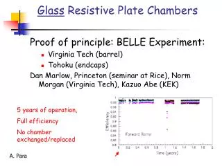
Glass Resistive Plate Chambers • BELLE Experiment: • Virginia Tech (barrel) • Tohoku (endcaps) Dan Marlow, Princeton (seminar at Rice), Norm Morgan (Virginia Tech) • Monolith Experiment (proposed at Grand Sasso): Carlo Gustavino • Virginia chambers at Fermilab Valery Makeev
RPC Principles of Operation Resistive paint Signal pickup (x) Glass plates 8 kV Signal pickup (y) Resistive paint +++++++++++++++ _ _ _ _ _ _ _ _ _ _ _ +++ +++++ _ _ _ _ _ _ _ Spacers A passing charged particle induces an avalanche, which develops into a spark. The discharge is quenched when all of the locally ( ) available charge is consumed. Before The discharged area recharges slowly through the high-resistivity glass plates. After
Plateau Curve 2 mm gap RPCs plateau at a fairly high voltage. Note the slight falloff in efficiency well above the plateau. This effect is real and typical.
Principles of Operation: I vs V Curve Glass RPCs have a distinctive and readily understandable current versus voltage relationship. • Low voltage • High voltage
Pulse Shape One interesting feature of RPCs is that the signal can be observed both using a pickup electrode and by viewing the light signal using a PMT. The pulses are large (~100 mV into 50 ohms) and fast (FWHM ~ 15ns) There is a very good correlation between the electronic and the light signal.
Current, pulse shape, efficiency • Pulse height, currents, plateau depend on: • Gas mixture • Electric field (HV/gap size) • Resistivity of the ink
Afterpulsing +++ ++++++++++++++ _ _ _ _ _ _ _ _ _ _ _ _ _ We (I.e. BELLE) observe a significant rate of afterpulsing. Typically the afterpulses are spaced by ~40 ns from the initial pulse (and other afterpulses). We believe that these pulses are caused by photons that escape the primary avalanche and initiate new streamers in a non-depleted region of the chamber. In some cases several afterpulses are observed
First result: signal from streamer mode Repond, Lia, (Argonne) • Gas: Freon/Argon/IsoButane at 62:30:8 • High Voltage: 7.5 KV or above • Cosmic ray signal (triggered by 3 layers of scintillator) PED + avalanche PED 1 streamer 2 streamers 3 streamers avalanche
Principles of Operation: Rate Capability +++ +++++ _ _ _ _ _ _ _ As noted, each discharge locally deadens the RPC. The recovery time is approximately Numerically this is (MKS units) Assuming each discharge deadens an area of , rates of up to can be handled with 1% deadtime or less. This is well below what is expected in our application.
Gas Mixture (Belle) • Traditional Gas Mixture • 64% Argon : 6% Freon 116 30% Isobutane • Constraints • Safety: gas should be non flammable: • mixture ---> 30% Argon : 62% Freon :8% Butane • Environment: Freon 116--> Freon R134A • Cost: Isobutane ---> Butane “silver”
Mechanical Details (Belle) Each module comprises two RPCs and orthogonal sets of readout strips. In principle, a single RPC would suffice, but the double layer provides redundancy and reduces the effect of irreducible efficiency losses, such as the spacers. It is easily seen that if the single layer inefficiency is , the two-layer inefficiency will be Typically
RPC Assembly at Va Tech To reduce assembly time, extruded strips were used instead of “button-like” spacers. This also provided a natural “mouse maze” to ensure uniform distribution of the gas.
Pickup Electrodes (Belle) The 5-cm-wide readout strips form a ~50 ohm transmission line. Cu-strip/Mylar Laminate (Sheldahl) Rigid foam 5 mm Cu sheet (for current return)
Problems and Solutions • Problem: Ink layers thin enough to provide the appropriate sheet resistance are susceptible to large uniformity variations (i.e., gaps). • Solution: mix white ink in with the black to raise the bulk resistivity of the ink. A thicker, more easily controlled, layer could then be applied. • Problem: “Mouse Maze” popping. In early versions of the RPCs, the glue joints for the spacers came loose. This caused the glass to bow out and resulted in an inefficiency loss in the central parts of the RPCs. • Solution: increase the width of the glue joint.
. . . Problems and Solutions • Problem: readout strip separation. In a number of cases the connection between the readout strips and the cables used to carry the signals off the modules came loose. • Solutions: • Institute more rigorous quality control during assembly. • Conduct post assembly conductivity tests using signal generator. • Rework as needed prior to installation.
Production of chambers at Virginia Tech Placing the top cover Gluing of spacers Applying a resistive layer
Virginia Chambers at Fermilab Valery Makeev Chambers have been stored in an ambient atmosphere for three years Eventually (see next slide) they work with efficiency >90%
Recovering efficiency == drying out Chambers stored for a long period of time accumulate water vapor. Water vapor leads to an increased current and reduced efficiency
Glass Spark Counter I (Monolith) It is an RPC with electrodes made of standard float glass instead of Bakelite with a completely different design approach developed at LNGS. (see G.Bencivenni et al. NIM A300 (1991) 572 C.Gustavino et al. To be published on NIM ) Gas Mixture : Argon/Freon/C4H10 = 48/48/4 Spacers by injection molding (2 mm) Noryl Envelope Float Glass Resistive film End caps by injection molding Thermoplastic soldering for gas sealing Easy and fast and cheap construction Ready for mass production.
Glass Spark Counter II _ + Glass Advantages Excellent surface uniformity (< 1 mm) and material homogeneity. No surface treatment needed. Cheap and well known technology. Relative high volume resistivity (1012Wcm) is not a limitation (Low rate environment). 175 cm Gas flow Design Advantages Gas flow optimization (spacers). Uncritical gas pressure operation (plastic envelope avoid changes on the detector gap). No graphite coating but adhesive resistive films for HV supply (Shintron, 3M, Dupont). HV contact without soldering (harmonic metal contact). Spacers clamped without glue with a tolerance 5 mm (uniform electric field) No graphite coating, gluing , soldering, linseed oil … fast assembling 25 cm
Trolley Assembling (Monolith) Discriminators 175 cm 175 cm Trolley G10 X Strips Layer (2.7 cm pitch) 25 cm Digital bus G10 Y Strips Layer(2.7 cm pitch) 2 cm thick 64 X and 64 Y strips/Trolley 1 TDC channel / Trolley HV Cables Gas fittings
Standardization of GSC production (Monolith) • Studies are in progress in order to define protocols for GSC standardization of large scale production production, to be transferred to external manufacturers • Production of glass with resistive coating has been identified as the most critical element for industrial production of GSCs • Two independent approaches have been followed • Export normal procedure to industry: identify a good varnish and a standard procedure for its application • Import industrial procedures in GSC production: find a coating which can be applied by industrial methods (screen printing) and result in good detector performance • A surface resistivity in the range 200-400 kOhm/square has been identified as optimal value
Standardization of GSCs • Production according to normal procedure • A graphite-based varnish, already used for large scale production of Iarocci-tubes (Politech varnish), has been chosen for resistive coating. It has produced predictable and stable GSC performance. • Systematic tests on coating procedure have been carried out in LNGS in collaboration with LNF (Candela, D’Incecco, Gustavino, Lindozzi, Menghetti, Santoni, Satta) • A protocol for varnishing, drying, cleaning and assembling has been estabilished and transferred to an external manufacturer • A first sample of chambers produced by the external manufacturer is now being tested in LNGS and LNF
GSCs – tests of normal production Resistivity vs. time ratio of resistivities vs. time Figures show the the time evolution of the surface resistivity of four chambers treated with the same varnish but slightly different procedures, resulting in different thickness of coating. The time dependence is the same for all samples. A stable condition is reached after 15 days, at a value of surface resistivity equal to the initial x2 (vertical scale shows resistance as measured between the two short edges of 0.25x1 m2 plates: divide it by 4 to obtain surface resistivity)
GSCs – tests of normal production The time evolution of the plateau of a chamber, from the first production by the external manufacturer, is shown. It is apparent a conditioning (burn-in) effect, which brings the chamber to ideal operating conditions after one week. The need of burn-in is attributed to non-ideal cleaning (see also results of Stockholm and Frascati). Improvements in the cleaning procedure are envisaged in order to reduce the burn-in time
Standardization of GSCs - part 2 • Import of industrial procedures • G.Bencivenni, A.Giuliano, G.Mannocchi, F.Murtas, P.Picchi, G.C.Trinchero The possibility to exploit materials especially developed to fit our needs and compatible with industrial large scale construction has been studied for resistive coating of GSC glass electrodes. The aim is to reduce costs and time and to improve performance and reliability. Techniques under investigation are: • Screen Printing using 2 components graphite paint • Screen Printing using resistive paint without graphite • Sputtering using metal oxides • Resistive Films Coating materials and painting techniques have been selected in order to fulfill the following requirements: • Resistance to the action of mechanical and chemical agents • Reliability, reproducibility and precision (thickness, homogeneity and dimensions) • Affordable costs • Compatibility with automatic procedures and large scale production
Screen Printing • Manual for small pre-series • Automatic for large scale production • Accurately controlled resistivity values • High reproducibility • High yield (30 m2/kg for 10 m dry thickness) • Surface resistivity depends from: • Material • Thickness • Ratio between Wires Distance/Wires Section • Thickness 5 m
Paints • 2 Components Graphite Paint • Good Glass adhesion • Resistivity controlled through Carbon/Insulating Pigments • Applicable with manual and automatic Screen Printing Equipment • Resistivity Sensitive to mechanical abrasion • Higher mechanical resistance could be obtained through 180° polimerisation • 500 K/ @ 10 m , 100 K/ @ 40 m • 2 Components Synthetic Resistive Paint • Excellent Glass adhesion • Resistant to common cleaning solvents • Resistivity obtained using metal oxides • Applicable with manual and automatic Screen Printing Equipment • High resistance to mechanical abrasion • 500 K/ @ 20 m , 100 K/ @ 50 m (spray painting)
Procedure • Float Glass Cutting & Grinding • Clean Room • Glass Cleaning (twice) • Optional pre-painting treatments • Automatic Screen Printing • Coated Glasses Packing & Shipping • Large Series ( 10000 m2 ) Automatic Procedures • 1000 m2/day • Small Series Semiautomatic Procedures • 1000 m2/week