Download

1 / 26
280 likes | 621 Views
Semiconductor Device Physics. Chapter 11 BJT Static Characteristics. Deviations from the Ideal. Chapter 11. BJT Static Characteristics. Common base. Deviations , due to model limitations. Common emitter. Chapter 11. BJT Static Characteristics. W. I E. I C. P+. N. P. . +.

E N D
Semiconductor Device Physics Chapter 11 BJT Static Characteristics
Deviations from the Ideal Chapter 11 BJT Static Characteristics • Common base Deviations, due to model limitations • Common emitter
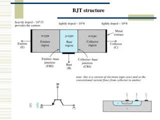
Chapter 11 BJT Static Characteristics W IE IC P+ N P + VEB Base-Width Modulation • Common-Emitter ConfigurationActive Mode Operation • Recalling two formulas, DpB(x) • If –VCB increases • W decreases • bdc increases • IC increases (VCB=0) Increasing –VCB x W 0
Chapter 11 BJT Static Characteristics Punch-Through • Punch-Through: E-B and C-B depletion regions in the base touch each other, so that W = 0. • As –VCB increases beyond the punch-through point, the E-B potential hill decreases and therefore increases the carrier injections and IC. WB=xnEB+xnCB
Chapter 11 BJT Static Characteristics Breakdown Mechanisms • In the common-emitter configuration, for high output voltage VCE, the output current IC will increase rapidly due to the two mechanisms: punch-through and avalanche. Punch-through Avalanche Increasing reverse bias of C-B junction
Chapter 11 BJT Static Characteristics Avalanche Multiplication • Holes [0] are injected into the base [1], then collected by the C-B junction. • Some holes in the C-B depletion region have enough energy do impact ionization [2]. • The generated electrons are swept into the base [3], then injected into the emitter [4]. • Each injected electron results in the injection of IEp/IEn holes from the emitter into the base [5]. pnp BJT • For each pair created in the C-B depletion region by impact ionization, (IEp/IEn) +1>bdc additional holes flow into the collector. • This means that carrier multiplication in C-B depletion region is internally amplified. M : multiplication factor
Chapter 11 BJT Static Characteristics Geometrical Effects • Emitter area is not equal to collector area. • Current does not flow in one direction only. • Series resistance. • Voltage drop occurs not only across the junction. • Current crowding. • Due to lateral flow, current is larger around emitter periphery than the collector periphery.
Chapter 11 BJT Static Characteristics Graded Base • Dopants are injected through diffusion. • More or less falling exponential distribution with distance into beneath of the semiconductor. • The doping within the base is not constant as assumed in ideal analysis. • A function of position, having maximum at E-B junction and minimum at C-B junction. • Creating a built-in electric field. • The electric field enhances the transport of minority carrier across the quasineutral width of the base. • Increase of IE and IC. xdiff : exponential decay constant
Chapter 11 BJT Static Characteristics Figures of Merit Due to recombination in emitter depletion region Gummel Plot Due to high level injection in base, base series resistance, and current crowding
Chapter 11 BJT Static Characteristics Polysilicon Emitter BJT • bdc is larger for a poly-Si emitter BJT as compared with an all-crystalline emitter BJT. • This is due to reduced dpE(x)/dx at the edge of the emitter depletion region. Lower mp • Continuity of hole current in emitter Shallower slope less JP higher g, b
Chapter 11 BJT Static Characteristics Summary on BJT Performance • High gain (bdc >> 1) • One-sided emitter junction, so that emitter efficiency g 1 • Emitter doped much more heavily than base (NE >> NB). • Narrow base, so base transport factor aT 1. • Quasi-neutral base width << minority-carrier diffusion length(W << LB). • IC determined only by IB (IC function of VCE or VCB) • One-sided collector junction, so that quasineutral base width W does not change drastically with changes in VCE or VCB. • Base doped more heavily than collector (NB > NC), W = WB – xnEB – xnCB for pnp BJT.
Semiconductor Device Physics Chapter 12 BJT Dynamic Response Modeling
Chapter 12 BJT Dynamic Response Modeling Qualitative Transient Response Saturation (ON) Load line Idealized switching circuit Cut-off (OFF)
Chapter 12 BJT Dynamic Response Modeling 3 3 2 2 1 1 4 4 5 5 Qualitative Transient Response cutoff active saturation saturation active
Chapter 12 BJT Dynamic Response Modeling Charge Control Relationships • A pnp BJT biased in the active mode has excess minority-carrier charge QB stored in the quasineutral base. • While Small • In steady state, Interpreted as average lifetime of an excess minority carrier
Chapter 12 BJT Dynamic Response Modeling Base Transit Time tt (Active mode) Interpreted as average time taken by minority carriers to diffuse across the quasineutral base
The lifetime of a minority carrier before it recombines in the base is much longer than the time it requires to cross the quasineutral base region Chapter 12 BJT Dynamic Response Modeling Relationship between tB and tt
Chapter 12 BJT Dynamic Response Modeling Example • Given an npn BJT with W = 0.1 μm and NB = 1017cm-3. Find tt. From Figure 3.5, mn = 801 cm2/(Vs)
Chapter 12 BJT Dynamic Response Modeling Turn-On Transient • During the turn-on transient: • The general solution is: • Initial condition: QB(0)=0, since transistor is in cutoff: tr: rise time, period of active mode
Chapter 12 BJT Dynamic Response Modeling Turn-On Transient IBBtB > ICCtt bdcIBB > ICC bdc > ICC/IBB • In saturation mode: bdc > bdc(saturation)
Chapter 12 BJT Dynamic Response Modeling Turn-Off Transient • During the turn-off transient: • The general solution is: • Initial condition: QB(0)=IBBtB: tsd : storage delay time
Chapter 12 BJT Dynamic Response Modeling Turn-Off Transient • The transient speed of a BJT depends on the amount of excess minority-carrier charge stored in the base and also the recombination lifetime tB. • By reducing tB, the carrier removal rate is increased, for example by adding recombination centers (Au atoms) in the base. • Tradeoff: bdc= tB/tt will decrease.
Chapter 12 BJT Dynamic Response Modeling Practical Considerations • The foregoing analysis was highly simplified to avoid excessive amount of mathematics. • More realistic iC transient response is shown below. • Added delay timetd (due to charging of junction capacitance)and fall timetf. Collector current (mathematical model) Collector current (actual form)
Chapter 12 BJT Dynamic Response Modeling Homework 8 • 1. (E11.36-B) • The base of a silicon npn bipolar transistor is WB = 0.8 μm wide. The doping concentrations are NB = 2×1016 cm–3 and NC = 1015 cm–3. Determine the punch-through voltage. • 2.(E11.37-B) • The base impurity doping level is NB = 3×1016 cm–3 and the base width is WB = 0.7 μm. If the required minimum punch-through voltage is determined to be Vpt = 70 V, calculate the highest level of collector doping. • 3. • Next slide. • Due: Monday, 02.12.2013.
Chapter 12 BJT Dynamic Response Modeling Homework 8 • 3.(EIE130.AF00F) • Consider a pnp silicon BJT of area A = 10–6 cm2 at 300 K. It operates in active region with VEB = 0.6 V and VCB = –1 V, so that WB = 0.6 μm. Assume that the emitter and collector regions are much longer than the respective minority carrier diffusion length. • Further data are given as follows: NE = 1019 cm–3, NB = 1017 cm–3, NC = 1015 cm–3, DE = 2 cm2/s, DB = 20 cm2/s, DC = 12 cm2/s, τE= 10–7 s, τB= τC= 10–6 • What is the common-emitter d.c current gain of this transistor? • What are the excess minority-carrier concentrations at the edges of the depletion regions (at A, B, C, and D in the diagram above). • Calculate the collector current.