Download
1 / 48
490 likes | 698 Views
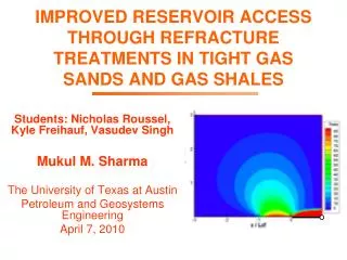
IMPROVED RESERVOIR ACCESS THROUGH REFRACTURE TREATMENTS IN TIGHT GAS SANDS AND GAS SHALES. Students: Nicholas Roussel, Kyle Freihauf, Vasudev Singh Mukul M. Sharma The University of Texas at Austin Petroleum and Geosystems Engineering April 7, 2010. Outline. Motivation and objectives

E N D
IMPROVED RESERVOIR ACCESS THROUGH REFRACTURE TREATMENTS IN TIGHT GAS SANDS AND GAS SHALES Students: Nicholas Roussel, Kyle Freihauf, Vasudev Singh Mukul M. Sharma The University of Texas at Austin Petroleum and Geosystems Engineering April 7, 2010
Outline • Motivation and objectives • Project participants, tasks and timing • Project tasks / deliverables • Progress to Date • Stress reorientation around producers and injectors: vertical and horizontal wells • Timing of refrac treatments • Multiple fracs in horizontal wells • Proppant placement in refracs • Summary
Motivation • Beating the decline curve in unconventional gas reservoirs requires continuous drilling and fracturing. • In a low gas price environment re-frac treatments offer a low cost alternative to drilling new wells. • Multiple fracs in horizontal wells are becoming the norm and the placement and geometry of these is impacted by stress reorientation. • Performance of re-fracs and multi-fracs is highly variable and must be made more reliable and predictable.
Project Objectives • Quantify the role played by stress reorientation on re-frac productivity improvement. • Improve our ability to predict refrac and multi-frac production enhancement, • Candidate well selection • Timing of refracs • Interaction of multiple fracs • Improve refrac and multi-frac design based on findings. • Calibrate the findings with field data.
Project Participants University of Texas at Austin Contact Mukul M. Sharma Professor of Petroleum & Geosystems Engineering Noble Energy Contact Michael ZollCompletions Manager Denver, CO Anadarko Petroleum Corp. Contact Jon David Caron Project Engineering Advisor BJ Services Contact Satya Gupta Senior Research Leader Tomball Technology Center PinnacleTechnologies Contact Steve Wolhart Region Manager
Project Tasks • Task 4. Stress Reorientation around Fractured Wells: Implications for Re-fracturing • Subtask 4.1 Data compilation in the Codell formation and the Barnett shale • Subtask 4.2 Stress re-orientation around fractured wells in shales and tight gas sands • Subtask 4.3 Models for stress reorientation in multi- fractured wells • Task 5. Selecting Timing and Candidate Wells for Re-fracturing • Task 6. Multi-frac Designs for Deviated and Horizontal Wells • Task 7. Proppant Placement in Re-fracturing Treatments (Vertical and Horizontal Wells) • Task 8. Use of Novel Proppant Placement Strategies in Re-fracturing Operations: Energized Fluids, hybrid fracs. • Task 9. Field Design of Re-Fracture Treatments in the Wattenberg Field • Task 10: Design, Implementation and Evaluation of Field Fracture Designs
Task 4: Stress Reorientation • Model is 3D and capable of handling, heterogeneity elasto-plasticity, multiple layers and anisotropy. • Stress reorientation due to two factors: • Poroelastic effects • Fracture opening • Constant pressure in vertical well and initial fracture. Bounding Layer Pay Zone Initial Fracture
Stress Reorientation Around Producers and Injectors Producer Injector Direction of Maximum Stress Stress Reversal occurs No Stress Reversal Angle of Stress Reorientation
Stress Reversal Region Producer Direction of Maximum Stress Isotropic point Fracture half-length Angle of Stress Reorientation Stress reversal region impacts direction of refracture in the field
Task 5. Selecting Timing and Candidate Wells for Re-fracturing Maximum areal extent of stress reversal λmax tmax = 4.13 years tmax = 1.3 days tmax = 1.15 months Optimum time for refracturing
Parameters Affecting the Orientation of the Re-frac The areal extent and timing of the stress reversal depend on: Fluid properties Reservoir characteristics Stress contrast Drawdown Thickness of the reservoir Mechanical properties of the bounding layers
Dimensionless Parameters (Berchenko et al., 1997; Siebrits et al., 1998; Roussel and Sharma, 2009) Dimensionless Time Dimensionless Stress Deviator Dimensionless Fracture Height Ratio Dimensionless Shear Modulus Ratio
Task 5. Selecting Timing and Candidate Wells for Re-fracturing • For a given set of reservoir and well conditions we can now estimate the extent of stress reorientation. This should be one of the primary criteria for re-frac candidate well selection. • The main results have been published. • “Quantifying Transient Effects in Altered-Stress Re-fracturing of Vertical Wells”, SPE 119522, Presented at the SPE Hydraulic Fracturing Meeting, Woodlands, 2009, Nicolas P. Roussel, Mukul M. Sharma.
Task 6. Re-fracture Designs for Deviated and Horizontal Wells t = 0
Stress Reorientation for a Production - Injection Well Pair t = 0
Stress Reorientation for 1 Production, 2 Injection Wells t = 0
Stress Reorientation for 2 Production, 1 Injection Well t = 0
Other Findings, Summary • An approaching fracture will go: • Away from a production well • Toward an injection well • Stress reorientation depends on: • Drawdown • Stress anisotropy • Moduli of sand and bounding layers • Stress reversal does occur in fractured producers. For a given set of reservoir / well conditions, we can now compute its, • Spatial extent • Timing
Field Validation We have computed stress reorientation in wells in the Barnett shale and in the Codell formation in the Wattenberg field. A complete dataset should include: Wellbore schematic and data Base map showing location of wells Details of frac and re-frac jobs Logs (dipole sonic) Microseismic Gas flow rate before / after re-frac Good initial agreement is obtained. Results of this comparison are in the SPE paper. Additional work ongoing with partner companies. January 20, 2009 DOE Project Kick-off Meeting 22
Transverse fractures Bounding layer Horizontal well Stress Reorientation Due to Fracture Opening • Opening of a fracture increases the stress in the direction of fracture opening i.e. increases the minimum horizontal stress. • Poro-elastic effects are negligible before production is initiated.
Stress Reorientation Limits the Number of Transverse Fractures Every fracture after the first one is affected by the stress reorientation. Fractures tend to reorient away from previous fractures in the vertical plane. This can lead to TSO or longitudinal fractures. We have quantified this effect. Top view Transverse fractures In-situ stress state After fracture opening Shmax Shmin Horizontal well Shmax Shmin
Stress Reorientation in Horizontal Well Fracturing Reoriented stress region 1 1 In-situ stress state S5 = 450 ft S10 = 320 ft Stress reversal region S90 = 140 ft Transverse fracture Horizontal well Direction of maximum horizontal stress Angle of stress reorientation
Quantifying the Concept of Minimum Fracture Spacing If the next fracture is initiated inside the stress reversal region, there is a possibility of: Longitudinal fracture Risk of screen-out To avoid longitudinal fractures, the minimum fracture spacing, should be greater than S90. To maintain transverse fractures the fracture spacing should be greater than S5. For any spacing between S90 and S5 fractures will deviate from the transverse plane. Ref:Nicolas P. Roussel, Mukul M. Sharma,SPE 127986,“Optimizing Fracture Spacing and Sequencing in Horizontal Well Fracturing” (2010).
Effect of Fracture Width, Stress Contrast on Minimum Fracture Spacing
Fracture Reorientation Because of Multiple Fractures 2 3 n n+1 1 Maximum S90 Stress reversal region Fracture spacing • Stress perturbations are cumulative as more fractures are added • The stress reversal region grows with each additional fracture • Fracture spacing should be at least greater than the maximum value of S90
Estimating Minimum Fracture Spacing, Consecutive Multiple Fractures n+1 n n+1 S5 = 600 ft S10 = 450 ft S90 = 230 ft Direction of maximum horizontal stress Angle of stress reorientation
Three Fracturing Sequences 3’ 2’ 1 2 3 4 5 1 2 5 3 1 2 3 1’ 4 1. Consecutive fracturing 3. Zipper fracs 2. Alternate fracturing
Alternate Fracturing (700-ft spacing) distance distance 1 2 Direction of maximum horizontal stress Angle of stress reorientation
Simultaneous Fracturing of Adjacent Wells: Zipper Fracs n+1’ n+1’ n+1 n+1 n’ S10 and S5 are significantly decreased (reoriented stress region) Parallel horizontal wells S5 = 400 ft S10 = 330 ft No diminution in S90 (stress reversal region) S90 = 230 ft n Direction of maximum horizontal stress Angle of stress reorientation
Alternate Fracturing Sequence Minimizes Fracture Spacing Minimum fracture spacing (S90): to avoid screen-out or longitudinal fractures Recommended fracture spacing (S5): to avoid fracture deviation from orthogonal path
Effect of Fracture SpacingOn Net Pressures – Multiple Fracs • Net pressure increase from toe to heel indicates stress interference. • Net pressure change depends on fracture dimensions and mechanical properties
Summary • Stress reorientation is the limiting factor in the spacing of multiple transverse fractures. • Our numerical model provides estimates of the minimum and recommended fracture spacing for any given set of reservoir, fracture properties. • The alternate fracturing technique minimizes fracture spacing. • Significant opportunities for higher production in horizontal well completions may be possible with the alternate fracturing method.
Task 7, 8. Use of Novel Proppant Placement Strategies in Re-fracturing Operations Status: Work is underway and we have some initial results.
Effect of Drawdown Pressure: Well A (EFRAC Results) Drawdown pressure is the main factor contributing the effectiveness of energized fluids
Effect of Inlet Foam Quality: Well A (EFRAC Results) Foams create higher conductivity Un-foamed fluids create more length
Summary of Progress to Date • Stress reorientation due to poroelastic and mechanical effects has been calculated for vertical, fractured and horizontal wells. • Key parameters and conditions that control this stress reorientation have been identified. • Re-frac candidate well selection is now possible using stress reorientation as a screening tool. • The optimum timing of re-frac treatments has been computed for the first time. • A new strategy for fracturing horizontal wells has been proposed to reduce the spacing between adjacent fractures.
Future Work • Further explore strategies for multiple fracturing in horizontal wells. • Continue to compare fracture reorientation results with well data from the Barnett and Codell formations. • Simulate different proppant placement strategies in re-fracture treatments.
Thank youQuestions? • I would like to Acknowledge: • RPSEA for their support. • Our partner companies (Anadarko, BJ Services, Noble Energy, Pinnacle) for collaboration and access to data. • Members of the Fracturing and Sand Control JIP at the University of Texas at Austin (Anadarko, BJ Services, BP, ConocoPhillips, Halliburton, Schlumberger, Shell, Total) for providing the cost sharing for this project.
Application of the Model to Typical Gas Reservoir Types • Parameter values for sandstone gas, tight gas and shale gas
Objectives • Use principal component analysis to determine the increase in production rate after a refracture treatment. • Use stress reorientation models to study the role played by stress reorientation vs other factors such as GOR and depletion. • Use these findings to recommend timing for refracs • Create a statistical, predictive model for • Production enhancement • Candidate well selection
Data Set • Refracture well data, approx. 4000 wells Anadarko, Noble Energy (1999 - 2008)
Time-Window for Refracturing: Oil Reservoirs Maximum areal extent of stress reversal λmax tmax = 2 days tmax = 6.5 months Optimum time for refracturing
Field Data for Validation A complete dataset would include: Gas properties (viscosity, compressibility) Reservoir parameters (k, Φ, E, ν) Bounding layer parameters (E, ν) Pressures (reservoir, wellbore) Estimates of stresses (direction and magnitude of maximum and minimum horizontal stresses)!! January 20, 2009 DOE Project Kick-off Meeting 47
Statistical AnalysisLinear Regression • Linear regression • Linear regression on original data • Scatter plots show weak relationship • Relating 1279 entries to 43 parameters
Milestones 1 Research Management Plan 2 Technology Status Assessment 3 Data compilation for the Codell formation 4 Data compilation for the Barnett shale 5 Stress reorientation model implementation and runs for Codell re-fracs 6 Stress reorientation model implementation and runs for Barnett shale re-fracs 7 Evaluation of fractured well performance in the Codell, Barnett and horizontal wells 8 Candidate well selection based on poro-elastic model and field data analysis 9 Design of re-frac treatments in the Codell, and Barnett based on simulations, new fluids and proppants 10 Design of re-frac treatments in horizontal wells based on simulations, new fluids and proppants 11 Implementation of re-frac treatments in the Codell, and Barnett (new designs). 12 Post frac evaluation of re-frac treatments in the Codell, Barnett and horizontal wells 13 Workshop in Houston to discuss results 14 Final report with all the findings from the study
Stress Reorientation in Horizontal Well Fracturing z Observation plane y x > 0 y > 0 z = 0 x • In the stress reversal region, risk of screen-out or longitudinal fracture. • Second fracture propagates away if initiated too close to the first fracture. • Ref: Nicolas P. Roussel • Mukul M. Sharma,SPE 127986,“Optimizing Fracture Spacing and Sequencing in Horizontal Well Fracturing” (2010). Direction of maximum horizontal stress Reoriented stress region 1 In-situ stress state 2 Stress reversal region Transverse fracture Horizontal well
Task 9, 10. Design of Re-Fracture Treatments in the Wattenberg Field • Wattenberg field, D-J basin • Codell formation • Thin sandstone layer • Low permeability, requires stimulation • Refractured since 1998 • Observations indicate that refracture performance is dictated by fracture-fluid viscosity profile (Ref: Miller, J. et al., 2004, SPE 90194) • Fracture reorientation has been reported (Ref: Wolhart, S. et al., 2007, SPE 110034) Source: USGS