Download

1 / 75
750 likes | 923 Views
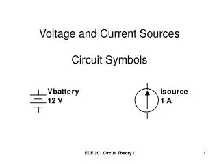
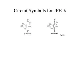
Circuit Symbols:. Battery Resistor Light-bulb Switch Wire. Three general types of circuits:. Closed Circuit - There is a complete loop with wires going from one side of the battery through a resistor(s) to the other side of the battery. Open Circuit - There is not a complete loop.

E N D
Circuit Symbols: Battery Resistor Light-bulb Switch Wire
Three general types of circuits: Closed Circuit - There is a complete loop with wires going from one side of the battery through a resistor(s) to the other side of the battery. Open Circuit - There is not a complete loop. Short Circuit - There is a complete loop, but it does not contain any resistors. Only Working Circuit
There are two ways to put resistors into a circuit. 1. Resistors can be in series OR 2. Resistors can be in parallel
Resistors in Series (like a trip to Costco) • Resistors are considered to be in series if the current must go through all of the resistors in order. • The current (amps) through all resistors in series is the same. • The voltage across resistors in series may be different • The rate of electron flow (or current) is determined by which resistor? The resistor with the largest amount of ohms.
R1 R2 R3 Combining (adding) Resistors Series Resistors Itotal = I1 = I2 = I3 Req = Rtotal = R1 + R2 + R3 Voltage is calculated with Ohm’s Law Q Amps
Resistors in Parallel (like a trip to Vons) • Resistors are considered to be in parallel if the current is shared between multiple resistors. • The current (amps) through all resistors in parallel may be different. • The voltage across all parallel resistors is the same. • Will a resistor with a large resistance have more or less current through it then a resistor with a small resistance? The resistor with a large resistance will have a smaller current then the resistor with the smaller resistance.
Combining (adding) Resistors Parallel Resistors Current is calculated with Ohm’s Law Vtotal = V1 = V2 = V3
Example 1: A circuit has three 8.0 W, 5.0 W and a 12 W resistors in series along with a 24 V battery. • Draw the circuit. • Calculate the total resistance of the circuit. • Calculate the total current through the circuit. • What is the current through each resistor? • Calculate the voltage across each resistor.
Example 2: A circuit has three resistors: 6.0 W, 4.0 W and a 12 W resistors in parallel along with a 24 V battery. • Draw the circuit. • Calculate the total resistance of the circuit. • Calculate the total current through the circuit. • What is the voltage across each resistor? • Calculate the current across each resistor.
Electrical Outlets • Electrical outlets provide electric potential (or the voltage) for any appliance plugged in to it. • In the United States ALL outlets provide 120 V (in Europe it is 240 V)
Light bulbs are made to be the only appliance plugged into a socket. • The power rating of a light bulb (25 W or 100 W…) is as if that bulb was the only bulb plugged in to a 120 V power source. • The resistance of a light bulb is calculated by knowing the power rating and the voltage (120 V) • Current and actual voltage used by a light bulb depends on the circuit.
Example 3: What will the power output be if an American-made 45 W light bulb is plugged in to a 310 V power source? • Using 120 V, calculate the resistance of the light bulb. • Using the resistance and the voltage of the new source, calculate the new power
As more identical resistors R are added to the parallel circuit shown, the total resistance between points P and Q … • Increases • Remains the same • Decreases R P Q …
As more identical resistors R are added to the parallel circuit shown, the total resistance between points P and Q … 1. Increases 2. Remains the same 3. decreases R P Q … Q
When one bulb is unscrewed, the other bulb will remain lit in which circuit… • I • II • Both • Neither Circuit II Circuit I
When one bulb is unscrewed, the other bulb will remain lit in which circuit… 1. I 2. II 3. both 4. neither Circuit I Circuit II
A 25W bulb and a 100W bulb are connected in series. Which bulb will glow brighter?
25W 100W 120V
The Light Bulbs are really Resistors A) Calculate the resistance for each resistor shown.B) Calculate the total resistance of the circuit.C) Calculate the current through each resistor.D) Calculate the power used by each resistor.E) Calculate the voltage across each resistor. 25W 100W 120V
Part A. 25W Bulb 100W Bulb
144 576 120V B) Calculate the total circuit resistance Rtotal Rtotal = R1 + R2 Series Resistors = 576 + 144 = 720
720 120V C) Calculate the total circuit current (I)
144 576 120V D) Calculate the Power used by each resistor. 25 W Bulb P = I2R = .1672 x 576 = 16 watts 100 W Bulb P = I2R = .1672 x 144 = 4 watts
96 volts 24 volts 144 576 120V E) Calculate the Voltage across each resistor. 25W Bulb V = IR = .167 x 576 = 96 volts 100W Bulb V = IR = .167 x 144 = 24 volts 120 volts
E) Consider the Percent Power Needed to Light Each Bulb 100 W Bulb 25 W Bulb Q
The circuit below consists of two identical light bulbs burning with equal brightness and a single 12V battery. When the switch is closed, the brightness of bulb A… A • Increases • Decreases • Remains unchanged
The circuit below consists of two identical light bulbs burning with equal brightness and a single 12V battery. When the switch is closed, the brightness of bulb A… • Increases 2. decreases 3. remains unchanged When the switch is closed, bulb B goes out because all of the current goes through the wire parallel to the bulb. Thus, the total resistance of the circuit decreases, the current through bulb increases, and it burns brighter. A Q
Which bird is in trouble when the switch is closed? • Bird 1 • 2) Bird 2 • 3) Neither • 4) Both 1 2
Which bird is in trouble when the switch is closed? 1) Bird 1 2) bird 2 3) neither 4) both 1 2
Charge flows through a light bulb. Suppose a wire is connected across the bulb as shown. When the wire is connected… • All the charge continues to flow through the bulb, and the bulb stays lit. • Half the charge flows through the wire, the other half continues through the bulb. • Essentially all the charge flows through the wire and the bulb goes out. • None of these. Q
Analyze the circuit: A) Calculate RtotalB) Calculate the current through each resistor.C) Calculate the voltage through each resistor. Parallel: 16 120V 32 32 16
Series: R123-4=8+16 R1234=24 16 120V 8
These are in parallel so their voltage is the same along with the total voltage Make chart: 16 120V 32 32 16 All these numbers will be the same.
These are in series so their current is the same along with the total current Make chart: 16 120V 8 All these numbers will be the same.
Fill out the chart with V=IR V = IR 120 = I (24) I = 5 A V = IR V = (5) (16) V = 80 V V = IR V = (5) (8) V = 40 V V = IR 40 = I (16) I = 2.5 A V = IR 40 = I (32) I = 1.25 A
Another way to do the problem (without the chart) I=V/R I=120v/24 I=5 amps 120V 5amps 24
V=IR V=(5)(16) V=80volts 16 80volts 5amps 120V V=IR V=(5)(8) V=40volts 8 40volts 120volts
I=V/R =40volts/16 =2.5 amps 5 amps 16 80volts 120V I=V/R =40volts/32 =1.25 amps 32 40 volts 32 16 5 amps
When the series circuit shown is connected, Bulb A is brighter than Bulb B. If the positions of the bulbs were reversed… • Bulb A would again be brighter • Bulb B would be brighter • They would be equal brightness
When the series circuit shown is connected, Bulb A is brighter than Bulb B. If the positions of the bulbs were reversed… • Bulb A would again be brighter • Bulb B would be brighter • They would be the same The bulbs are connected in series, so the same current passes through both of them. Different brightnesses indicate different filament resistances. Bulb A is NOT brighter because it is “first in line” for the current of the battery! After all, electrons deliver the energy, and they flow from negative to positive --- in the opposite direction!
Example: Find the voltage and current for each resistor. 6 3 6 3 4 2 12 18 volts
6 3 6 3 4 2 12 18 volts
3 3 3 4 2 12 18 volts
3 3 3 4 2 12 18 volts
6 3 4 2 12 18 volts
6 3 4 2 12 18 volts
6 3 3 2 18 volts