Advanced LIGO
410 likes | 432 Views
Learn about the design features and performance goals of the Advanced LIGO project, aimed at detecting gravitational waves and advancing GW astronomy. Discover the significant occurrences and future prospects of this cutting-edge detector.

Advanced LIGO
E N D
Presentation Transcript
Advanced LIGO David Ottaway,for the LIGO Scientific Collaboration Aspen Winter Conference Feb 2004 LIGO Scientific Collaboration
Advanced LIGO • LIGO mission: detect gravitational waves and initiate GW astronomy • Next detector • Should have assured detectability of known sources • Should be at the limits of reasonable extrapolations of detector physics and technologies • Must be a realizable, practical, reliable instrument • Should come into existence neither too early nor too late Advanced LIGO LIGO Scientific Collaboration
Initial and Advanced LIGO • Factor 10 better amplitude sensitivity • (Reach)3 = rate • Factor 4 lower frequency bound • Factor 100 better narrow-band • NS Binaries: • Initial LIGO: ~20 Mpc • Adv LIGO: ~350 Mpc • BH Binaries: • Initial LIGO: 10 Mo, 100 Mpc • Adv LIGO : 50 Mo, z=2 • Known Pulsars: • Initial LIGO:e3x10-6 • Adv LIGOe2x10-8 • Stochastic background: >> Initial LIGO: Ω~3x10⁻⁶ >> Adv LIGO: Ω~ 3x10⁻⁹ LIGO Scientific Collaboration
Design features 40 KG SAPPHIRETEST MASSES ACTIVE ISOLATION QUAD SILICASUSPENSION 180 W LASER,MODULATION SYSTEM PRM Power Recycling Mirror BS Beam Splitter ITM Input Test Mass ETM End Test Mass SRM Signal Recycling Mirror PD Photodiode LIGO Scientific Collaboration
So what changes … Subsystem Initial LIGO Advanced LIGO Interferometer Power recycling Power and Signal Recycling Output RF read-out DC read out with output mode cleaner PSL 10 Watt MOPA 180 W Injection-Locked Oscillator P/P ~ 10-8 1/Hz at 100 Hz P/P ~ 2 10-9 1/Hz at 10 Hz Input Optics 300 g single suspension 3 Kg triple suspensions Adaptable optics, better isolators and EOMs Core Optics Fused Silica (10 Kg) Sapphire / Fused Silica Optics (40 Kg) g1 g2 = (0.71)(0.43) = 0.3 g1 g2=(1-4/2.08)(1-4/2.08)=0.85 Coatings Phi ~4 10-4 Si O2/Ta O5 Phi ~ 5 10-5 Coating material TPD Seismic Passive attenuation Active 6 dof system with HEPI (Init. LIGO extra) Suspensions Single loop wire Quad Suspensions with fused silica fibers ATC Added later ? Full thermal compensation system LIGO Scientific Collaboration
System prototyping • Initial LIGO experience: thorough testing off-site necessary • Very significant feature in Advanced LIGO plan: testing of accurate prototypes in context • Two major facilities: • MIT LASTI facility – full scale tests of seismic isolation, suspensions, laser, mode Cleaner • Caltech 40m interferometer – sensing/controls tests of readout, engineering model for data acquisition, software • Support from LSC testbeds • Gingin – thermal compensation • Glasgow 10m – readout • Stanford ETF – seismic isolation • GEO600 – much more than a prototype! LIGO Scientific Collaboration
10-21 10-22 10-23 10-24 10 Hz 100 Hz 1 kHz Anatomy of the projected Adv LIGO detector performance • Newtonian background,estimate for LIGO sites • Seismic ‘cutoff’ at 10 Hz • Suspension thermal noise • Test mass thermal noise • Unified quantum noise dominates at most frequencies for fullpower, broadband tuning Initial LIGO Advanced LIGO NS-NS Tuning LIGO Scientific Collaboration
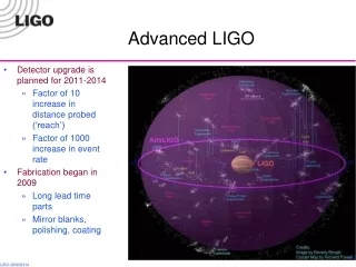
Baseline plan • Initial LIGO Observation at design sensitivity 2004 – 2006 • Significant observation within LIGO Observatory • Significant networked observation with GEO, VIRGO, TAMA • Structured R&D program to develop technologies • Conceptual design developed by LSC in 1998 • Cooperative Agreement carries R&D to Final Design • Now: Proposal is for fabrication, installation positively reviewed“…process leading to construction should proceed” • Long-lead purchases planned for 2004, real start 2005 • Sapphire Test Mass material, seismic isolation fabrication • Prepare a ‘stock’ of equipment for minimum downtime, rapid installation • Start installation in 2007 • Baseline is a staggered installation, Livingston and then Hanford • Coincident observations by 2010 • Optimism for networked observation with other ‘2nd generation’ instruments LIGO Scientific Collaboration
Significant Occurrences in 2003/04(Probably not covered by other talks) • Advanced LIGO proposal was submitted • Thermal noise in coatings • Dominant loss mechanism in Initial LIGO coatings is Tantalum • Direct measurement of coating thermal noise by two groups • New materials – Hafnia, Titania, Alloys • DC readout chosen for baseline design readout • Started construction of Advanced LIGO Seismic prototypes • Intensity Stability at 10-8 level at 10 Hz • Radiation pressure instability realized (Seidels and Sigg) • Advanced LIGO will use near concentric cavities • Radiation pressure instability occurs at 200 kWs circulating power LIGO Scientific Collaboration
Beyond Advanced LIGO • Advanced LIGO has a large potential for incremental improvement • Large areas of strain frequency space can be improved without complete reconstruction of the detector • Some potential improvement areas • Thermoelastic and thermal noise ( flat top beams) • Optical Noise (QND) • Gravity gradient noise (Feed forward subtraction) • Tunability (Variable reflectivity signal recycling mirror) LIGO Scientific Collaboration
Flat-Topped Beams • Improve detector performance by reducing the effect of thermo-elastic noise • Achieved by flattening the intensity of the light field • Proposed by Thorne et al. • Very near flat cavities unstable for high power operation • Preliminary experiment being organized at Caltech LIGO Scientific Collaboration
OBJECTIVE: Reduce Thermoelastic Noise in LIGO-II, to Take Advantage of the Low Optical Noise Thermoelastic Noise Flat Topped Beam EffectsSapphire Mirror Substrates LIGO Scientific Collaboration
QND and Squeezing • Inject squeezed vacuum into the dark port • Need 10dB of squeezing at 100 Hz • Amplitude filtering using mode cleaner cavities (Corbitt et al.) • Short filter cavities to vary the squeeze angle (Buanno et al.) • Vacuum tanks are already in place • Plot courtesy of Thomas Corbitt LIGO Scientific Collaboration
10-22 10-23 10-24 10-25 100 1K 10 K Frequency (Hz) Thermoelastic Detuning = 0.12, SRM Ref. = 0.93 Detuning = 0.025, SRM Ref. = 0.93 Detuning = 0.025, SRM Ref. = 0.99 Detuning = 0.12, SRM Ref. =0.99 Variable Reflectivity SRMs • Signal recycling adjustment allows instrument to be tuned for different searches • Tunable SRM allows rapid changes in search strategy • Multiple approaches being researched • Thermally tuned etalon (GEO 600) • Suspended cavity or Michelson (ANU) LIGO Scientific Collaboration
Test Mass Array of accelerometers Gravity Gradient Subtraction • Gravity gradient noise caused by local variations in the density of surrounding earth • Dominant contribution is surface waves • Vertical accelerometers used to monitor motion and infer density changes • Need to be spaced ~ ¼ wavelength apart => ~ 4 m at 20 Hz LIGO Scientific Collaboration
Advanced LIGO • Advanced LIGO promises exciting astrophysics • Advanced LIGO has been proposed and is in an advanced state of research and development • Advanced LIGO should bring maturity to the science of Gravitational Wave Detection • The baseline design will allow incremental improvements to be added when cutting edge technology becomes more available and reliable • A broad community effort with significant international support LIGO Scientific Collaboration
Laser 40 KG SAPPHIRETEST MASSES ACTIVE ISOLATION QUAD SILICASUSPENSION LIGO Scientific Collaboration
output NPRO QR f f EOM FI BP FI modemaching YAG / Nd:YAG 3x2x6 optics QR f f BP YAG / Nd:YAG / YAG HR@1064 f 2f f 3x 7x40x7 HT@808 20 W Master High Power Slave Pre-stabilized Laser • Require the maximum power compatible with optical materials • Three approaches studied by LSC collaboration – stable/unstable slab oscillator (Adelaide), slab amplifier (Stanford), end-pumped rod oscillator (Laser Zentrum Hannover (LZH)); evaluation concludes that all three look feasible • Baseline design continuing with end-pumped rod oscillator, injection locked to an NPRO • 2003: Prototyping well advanced – ½ of Slave system has developed 87 W LIGO Scientific Collaboration
Pre-stabilized laser • Overall subsystem system design similar to initial LIGO • Frequency stabilization to fixed reference cavity, 10 Hz/Hz1/2 at 10 Hz required (10 Hz/Hz1/2 at 12 Hz seen in initial LIGO) • Intensity stabilization to in-vacuum photodiode, 2x10⁻⁹ ΔP/P at 10 Hz required (1x10⁻⁸ at 10 Hz demonstrated) • Max Planck Institute, Hannover leading the Pre-stabilized laser development • Close interaction with Laser Zentrum Hannover • Experience with GEO-600 laser, reliability, packaging • Germany contributing laser to Advanced LIGO LIGO Scientific Collaboration
Intensity Stabilization • Our approach: • Very low noise AC-coupled PD • Low voltage low noise parts in the signal path • Beam geometry stabilized by PMC LIGO Scientific Collaboration
Input Optics, Modulation 40 KG SAPPHIRETEST MASSES ACTIVE ISOLATION QUAD SILICASUSPENSION LIGO Scientific Collaboration
Input Optics • Provides phase modulation for length, angle control (Pound-Drever-Hall) • Stabilizes beam position, frequency with suspended mode-cleaner cavity • Matches into main optics (6 cm beam) with suspended telescope • Design similar to initial LIGO but 20x higher power • Challenges: • Modulators • Faraday Isolators LIGO Scientific Collaboration
Input Optics • University of Florida leading development effort • As for initial LIGO • High power rubidium tantanyl phosphate (RTP) electro-optic modulator developed • Long-term exposure at Advanced LIGO power densities, with no degradation • Faraday isolator from IAP-Nizhny Novgorod • thermal birefringence compensated • Ok to 80 W – more powerful test laser being installed at LIGO Livingston LIGO Scientific Collaboration
Test Masses 40 KG SAPPHIRETEST MASSES ACTIVE ISOLATION QUAD SILICASUSPENSION 200 W LASER,MODULATION SYSTEM LIGO Scientific Collaboration
Test Masses / Core Optics • Absolutely central mechanical and optical element in the detector • 830 kW; <1ppm loss; <20ppm scatter • 2x10⁸ Q; 40 kg; 32 cm dia • Sapphire is the baseline test mass/core optic material; development program underway • Characterization by very active and broad LSC working group • Low mechanical loss, high density, high thermal conductivity all desirable attributes of sapphire • Fused silica remains a viable fallback option Full-size Advanced LIGO sapphire substrate LIGO Scientific Collaboration
Core Optics Compensation Polish • Fabrication of Sapphire: • 4 full-size Advanced LIGO boules grown(Crystal Systems); 31.4 x 13 cm; two acquired • Mechanical losses: requirement met • recently measured at 200 million (uncoated) • Bulk Homogeneity: requirement met • Sapphire as delivered has 50 nm-rms distortion • Goodrich 10 nm-rms compensation polish • Polishing technology: • CSIRO has polished a 15 cm diam sapphire piece: 1.0 nm-rms uniformity over central 120 mm(requirement is 0.75 nm) • Bulk Absorption: • Uniformity needs work • Average level ~60 ppm, 40 ppm desired • Annealing shown to reduce losses before LIGO Scientific Collaboration after
Mirror coatings 40 KG SAPPHIRETEST MASSES ACTIVE ISOLATION COATINGS QUAD SILICASUSPENSION 200 W LASER,MODULATION SYSTEM LIGO Scientific Collaboration
Test Mass Coatings • Optical absorption (~0.5 ppm), scatter meetrequirements for (good) conventional coatings • Thermal noise due to coating mechanical loss recognized; LSC programput in motion to develop low-loss coatings • Series of coating runs – materials, thickness, annealing, vendors • Measurements on a variety of samples • Ta2O5 identified as principal source of loss • Test coatings show somewhat reduced loss • Alumina/Tantala • Doped Silica/Tantala • Need ~5x reduction in loss to make compromise to performance minimal • Expanding the coating development program • RFP out to 5 vendors; have selected 2 • Direct measurement via special purpose TNI interferometer • First to-be-installed coatings needed in ~2.5 years – sets the time scale Requiredcoating Standardcoating LIGO Scientific Collaboration
Thermal Compensation 40 KG SAPPHIRETEST MASSES ACTIVE ISOLATION COATINGS QUAD SILICASUSPENSION 200 W LASER,MODULATION SYSTEM LIGO Scientific Collaboration
ITM Compensation Plates Shielded ring compensator test PRM ITM SRM 20 nm Optical path distortion 0 5 mm 10 15 Active Thermal Compensation • Removes excess ‘focus’ due to absorption in coating, substrate • Allows optics to be used at all input powers • Initial R&D successfully completed • Ryan Lawrence MIT PhD thesis • Quasi-static ring-shaped additional heating • Scan to complement irregular absorption • Sophisticated thermal model (‘Melody’) developed to calculate needs and solution • Gingin facility (ACIGA) readying tests with Lab suspensions, optics • Application to initial LIGO currently being installed on Hanford 4 km interferometer • Thermal correction of a mirror achieved at GEO 600 LIGO Scientific Collaboration
Seismic Isolation 40 KG SAPPHIRETEST MASSES ACTIVE ISOLATION COATINGS QUAD SILICASUSPENSION 200 W LASER,MODULATION SYSTEM LIGO Scientific Collaboration
Isolation: Requirements • Render seismic noise a negligible limitation to GW searches • Newtonian background will dominate for frequencies less than ~15 Hz • Suspension and isolation contribute to attenuation • Reduce or eliminate actuation on test masses • Actuation source of direct noise, also increases thermal noise • Acquisition challenge greatly reduced • In-lock (detection mode) control system challenge is also reduced Seismiccontribution Newtonianbackground LIGO Scientific Collaboration
Isolation: Two-stage platform • Choose an active approach: • high-gain servo systems, two stages of 6 degree-of-freedom each • Allows extensive tuning of system after installation, operational modes • Dynamics decoupled from suspension systems • Lead at LSU • Stanford Engineering Test Facility Prototype fabricated • Mechanical system complete • Instrumentation being installed • First measurements indicate excellent actuator – structure alignment LIGO Scientific Collaboration
Isolation: Pre-Isolator • External stage of low-frequency pre-isolation ( ~1 Hz) • Tidal, microseismic peak reduction • DC Alignment/position control and offload from the suspensions • 1 mm pp range • Lead at Stanford • Prototypes in test and evaluation at MIT for early deployment at Livingston in order to reduce the cultural noise impact on initial LIGO • System performance exceeds Advanced LIGO requirements LIGO Scientific Collaboration
Suspension 40 KG SAPPHIRETEST MASSES ACTIVE ISOLATION COATINGS QUAD SILICASUSPENSION 200 W LASER,MODULATION SYSTEM LIGO Scientific Collaboration
Suspensions: Test Mass Quads • Adopt GEO600 monolithic suspension assembly • Requirements: • minimize suspension thermal noise • Complement seismic isolation • Provide actuation hierarchy • Quadruple pendulum design chosen • Fused silica fibers, bonded to test mass • Leaf springs (VIRGO origin) for verticalcompliance • Success of GEO600 a significant comfort • 2002: All fused silica suspensions installed • PPARC funding approved: significant financial,technical contribution; quad suspensions, electronics, and some sapphire substrates • U Glasgow, Birmingham, Rutherford • Quad lead in UK LIGO Scientific Collaboration
Suspensions: Triples • Triple suspensions for auxiliary optics • Relaxed performance requirements • Uses same fused-silica design, control hierarchy • Prototype of Mode Cleaner triple suspension fabricated • Damping of modes demonstrated • To be installed in MIT LASTI test facility in fall of 2003 • Fit tests • Controls/actuation testing LIGO Scientific Collaboration
GW Readout 40 KG SAPPHIRETEST MASSES ACTIVE ISOLATION COATINGS QUAD SILICASUSPENSION 200 W LASER,MODULATION SYSTEM LIGO Scientific Collaboration
GW readout, Systems • Signal recycled Michelson Fabry-Perot • Offers flexibility in instrument response, optimization for technical noises, sources • Can also provide narrowband response – ~10-24/Hz1/2 up to ~2 kHz • Critical advantage: can distribute optical power in interferometer as desired • Three table-top prototypes give direction for sensing, locking system • Glasgow 10m prototype: control matrix elements confirmed • Readout choice – DC rather than RF for GW sensing • Offset ~ 1 picometer from interferometer dark fringe • Best SNR, simplifies laser, photodetection requirements • Caltech 40m prototype in construction, early testing • Complete end-to-end test of readout, controls, data acquisition High-frequency narrowbanding Thermal noise Low-frequencyoptimization LIGO Scientific Collaboration
Scope of proposal • Upgrade of the detector • All interferometer subsystems • Data acquisition and control infrastructure • Upgrade of the laboratory data analysis system • Observatory on-line analysis • Caltech and MIT campus off-line analysis and archive • Virtually no changes in the infrastructure • Buildings, foundations, services, 4km arms unchanged • Present vacuum quality suffices for Advanced LIGO – 10-7 torr • Move 2km test mass chambers to 4km point at Hanford • Replacement of ~15m long spool piece in vacuum equipment LIGO Scientific Collaboration
Upgrade of all three interferometers • In discovery phase, tune all three to broadband curve • 3 interferometers nearly doubles the event rate over 2 interferometers • Improves non-Gaussian statistics • Commissioning on other LHO IFO while observing with LHO-LLO pair • In observation phase, the same IFO configuration can be tuned to increase low or high frequency sensitivity • sub-micron shift in the operating point of one mirror suffices • third IFO could e.g., • observe with a narrow-band VIRGO • focus alone on a known-frequency periodic source • focus on a narrow frequency band associated with a coalescence, or BH ringing of an inspiral detected by other two IFOs LIGO Scientific Collaboration