Download
1 / 23
230 likes | 384 Views
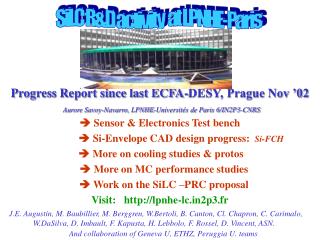
SiLC R&D activity at LPNHE-Paris. Progress Report since last ECFA-DESY, Prague Nov ’02 Aurore Savoy-Navarro, LPNHE-Universités de Paris 6/IN2P3-CNRS. Sensor & Electronics Test bench Si-Envelope CAD design progress: Si-FCH More on cooling studies & protos

E N D
SiLC R&D activity at LPNHE-Paris Progress Report since last ECFA-DESY, Prague Nov ’02Aurore Savoy-Navarro,LPNHE-Universités de Paris 6/IN2P3-CNRS Sensor & Electronics Test bench Si-Envelope CAD design progress: Si-FCH More on cooling studies & protos More on MC performance studies Work on the SiLC –PRC proposal Visit: http://lpnhe-lc.in2p3.fr J.E. Augustin, M. Baubillier, M. Berggren, W.Bertoli, B. Canton, Cl. Chapron, C. Carimalo, W.DaSilva, D. Imbault, F. Kapusta, H. Lebbolo, F. Rossel, D. Vincent, ASN. And collaboration of Geneva U, ETHZ, Peruggia U. teams
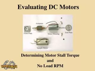
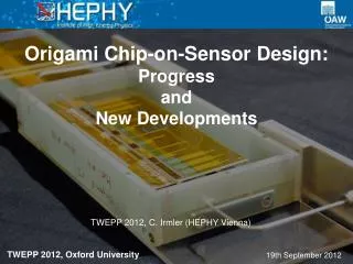
1.- SENSOR & ELECTRONICS TEST BENCH Major step forward: The prototype long ladder has been built following the AMS recipes to build long ladders: Geneva U for assembling & mounting of the individual sensors that constitutes the long ladder, ETHZurich@ CERN bonded the sensors and the VFE electronics, and also Peruggia U. + Paris-LPNHE contributions The prototyped long ladder is a key-element for the test-bench It enable us to start an extensive study of the characteristics both of the long microstrips and the VFE electronics linked to it; S and N evolution wrt strip and shaping time length, with temperature etc… and also testing various VFE’s=>design of new VFE This test activity is starting now at the Lab
AMS-01 Silicon precision cut ~ 3.5 m t1 t2 l1 l2 The distance between the reference marks on the silicon and the edge after the cut => the precision of the cutting itself
AMS-01 Silicon alignement The residual of the ladder metrology (after gluing)
The Prototype ladder & VFE outputs The p-side, 110 -RO pitch The leakage current of all strips of each sensor were measured Ladder is made of 7 AMS, 4’’ sensors: 4.1x7.2 cm2, 300 thick Today and tomorrow: first measurements of the ladder on Geneva test bench The n-side, 220 RO pitch A lot was learnt by our technical team on the details of the construction of long ladder: VALUABLE for the next times (from ``handmade’’to large scale fabrication)
The output-kapton design • allows: • Variable lengths: 28, 56, 112, and 224 cm strip-length • Change VFE (cutting the kapton) First tests on VA-64-hdr & VA-1(better noise perf., lower dynamic range wrt to other VA) Next step: design of a new VFE (in September) =>foundry Jan’04
2.- Progress on CAD design of the Si-envelope The honeycomb structure The ladder made of 6 sensors The SET-drawer For 5 ladders Detailed CATIA-based design of SET and SIT
Importance of the tracking at large angle growing interest on the Si-FCH design The physics interest of the large angle region is growing with the with the increase of Ecm. Physics both standard and beyond standard (SUSY, Xdim) is giving several appealing scenarios that require a good measurement of tracks including down to very low angles wrt beam axis. The LPNHE-Paris team is interested in the Si-FCH and is thus pursuying the study of the large angle region in two ways: 1) Physicist’s simus (SGV and to be started: GEANT4-based simu) study of the design (XUV geometry, number of layers, long strips ? How long? etc….), and of detector performances of Si-FCH (Momentum resolution, occupancy). Details from TESLA beam needed as input info. 2) CAD mechanical design studies with as drawback to 1): def of geometry DB for the Si-FCH in GEANT 4 simu.
Si-FCH Design & Performance studies with SGV-based simulations Low Pt region < 25 GeV/c High Pt region > 25 GeV/c 4 XUV planes are presently considered. Impulsion resolution of: TPC+straw tubes (100m reso/pt) wrt TPC+Si-FCH (25m reso/pt) Si-FCH better than straw tubes for large impulsion and when the angle wrt beamincreases
Evolution of the Si-FCH design: from projective to XUV Chicago Wkshp: Jan’02 Projective=> short strips Going from projective to XUV geometry St-Malo: April ‘02 XUV => long strips possible thus less channels & easy to build
New Si-FCH design based on long ladders Single sided designs: {XXXX} + {UUUU} + {VVVV} {XUV}-triplet The region of cut (if any) and around beam axis must be studied and carefully designed to avoid dead regions Double-sided (true or false) with: {X} + {UVUVUVUV}+{X}
More on: Cooling studies Two approaches in parallel: Mechanical prototype CAD dedicated simu package
Comparisons between proto measurements and CAD simus computations Tunning the simulations with the measurement results on the mechanical prototype New measurements on prototype surrounding it with an epoxy structure (more stringent than reality) that mimics the honeycomb struture
Further progress on the simulation studiesLC-Note to be submitted in about one weekand on: http://lpnhe-lc.in2p3.fr/lcnotes • Studies are SGV-based (see presentation by M. Berggren at Simu session) • Main outcomes of this present work: • Study on the best geometry design for the proposed SET device: • The SET detector should be made of 3 layers, with one double • sided, packed as closely as possible, and with the best possible • point resolution. Making the detector as thin as possible is • useful but a second priority wrt previous points. • Momentum resolution with TPC with or without SET (next page) • Same for the Si-FCH (see some transparencies above) • Hit density in SET • Hit density in Forward tracking: being started • Effect of SET device on gammas Remark: Although a fast simu, SGV includes : mulitple scattering, materials, spiralling of low Pt charged tracks etc…. (see SGV Web site)
Low Pt range: up to 25 GeV/c High Pt range: up to 250 GeV/c 1GeV/c 4.5 GeV/c Assumptions: TPC reduced to 155cm, pt resolution = 180 m Under these assumptions: An improvement up to 20% is observed at high momenta and, For low momenta the 2 reso curves cross at 4.5 and 1 GeV/c (tracks < 1 GeV/c do not reach the SET) => modest (<5%) deterioration between 1 and 4,5 with SET, rising up to 10% at 1.5GeV/c
Worldwide R&D activity for Si-tracking at the LC from 2003 to end 2006, With as main objectives, generic R&D on Si-sensors ( strips, SDD, new SS-sensors) VFE, readout and RT processing electronics Mechanics: XXXXXthin detector Simus studies & developments Test bench, including test beams Calibration & Monitoring issues Submission of a proposal for the next PRC: May 7th-8th Setting-up of the SiLC collaboration: PRC See asn’s presentation on March 31st at the International LC tracking + Muon Report VRVS Conference – NIKHEF, see tracking Website And: http://lpnhe-lc.in2p3.fr / Click on Amsterdam31