Download
1 / 22
220 likes | 256 Views
Upgrade to the Hall A Compton Polarimeter to provide enhanced accuracy for polarization experiments, enabling high precision Parity violating experiments. The upgrade includes a new Electron Detector with high-resolution silicon microstrips, a new Photon Detector, and a High Power Green Fabry-Perot Cavity to improve the system’s analyzing power. The project involves multiple institutions collaborating to increase the Figure-of-Merit. Detailed specifications and plans are in place for the electron detector, photon detector, and the Green Fabry-Perot Cavity. The initiative aims to reduce systematic uncertainties and boost the overall performance of the polarimeter setup, with simulations showing promising results.

E N D
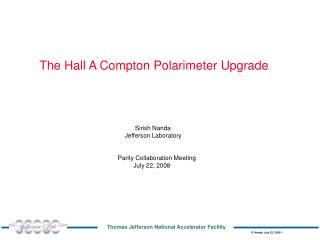
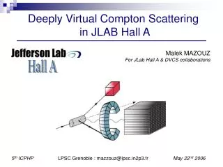
The Hall A Compton Polarimeter Sirish Nanda Jefferson Laboratory Hall A Collaboration Meeting June 22, 2007
e- e- Compton Polarimetry s + E,E’ k,k’ s - <Ath>=2 % kmax=340 MeV • Figure-of-Merit ~ s x A2 ~ k2 x E2
The Hall A Compton Polarimeter Upgrade Motivation: Improve accuracy of polarization experiments by providing 1% beam polarimetery down to 1 GeV. High precision Parity violating experiments are feasible with this upgrade Scope: • New Electron Detector • High resolution silicon microstrips to improve tracking resolution New Photon Detector Improve systematic uncertainties experienced in the counting method While preserving counting abilities High Power Green Fabry-Perot Cavity Twice the Analyzing power of present IR cavity Four-fold increase in Figure-of-Merit Participating Institutions:Jefferson Lab, Saclay, Syracuse, Clermont-Ferrand, Uva, Duke,Carnegie-Mellon
Expected Performance Simulation by David Lhuillier < 1% error @0.85 GeV obtained in about 4 hrs with 50 uA beam
Electron Detector LPC Clermont-Ferrand (contact: B. Michel) • Specification • 768 ch 240 mm pitch silicon mstrips • 4 Planes, 192 strips/plane, 1 cm spacing between planes • 120 mm Vertical motion to allow coverage of Compton Edge from 0.8-11 GeV • New custom front-end, FPGA trigger module (ETROC) • New DAQ and Analysis Software
Electron Detector Status • Detector & Electronics (Michel Brossard) • Four planes of Silicon microsrtip delivered by Canberra Systems • Front-end analog electronics completed • ETROC Trigger system in fabrication • Test scheduled for July/Aug 07 • Fifth spare microstrip ordered from Canberra • Mechanical (Francois Daudon) • Detector chamber design completed and approved • Parts in fabrication • Vertical motion controller to be done • DAQ (Alex Camsonne) • CODA readout for new ETROC • New electron event decoder • The new detector will be compatible with old DAQ and Analysis with only 48 strips active Just in case… • Support Structure and Installation (Alan Gavalya, Tim Whitlach, Chris Curtis, Ed Folts…) • Survey alignment scheme finalized • Support structure in design • Preliminary installation plan developed On track for Jan-Feb 08 installation
Photon DetectorCarnegie-Mellon University (Contact: Gregg Franklin) • Calorimeter • Simulation and Conceptual design Completed • Single large crystal GSO/Single PMT • High light output, fast decay time (less than 60 ns) • Preserve triggered counting capabilities. • Small sample test at CMU this summer with loaner from the detector group • Crystal procurement negotiations with Hitachi in Progress • Integrating DAQ • Flash ADC prototype has been beam tested (R. Michaels) • Improvements needed • New ADCs in procurement • Further beam tests planned for 2007/8
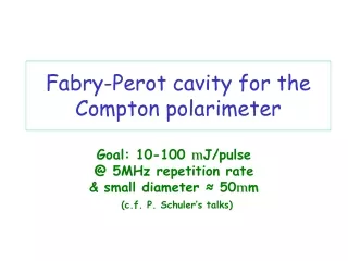
Green Fabry-Perot CavityJefferson Lab and Duke University (contact: SN) • Specification • Intracavity power 1.5 kW • Wavelength 532 nm • Mode CW, TEM00 • CIP Spot size () 65 m • Locking PDH • Solutions • Primary: a) Tunable “smart” single pass Green Laser -> “Passive” High Finesses cavity, • Feedback to laser PZT to lock (Botao Jia) • b) Tunable “smart” IR Laser + single pass PPLN SHG -> “Passive” High Finesse • Cavity, Feedback to laser PZT (Diana Parno) • Alternate: non-tunable “dumb” Green Laser + Electro-optic frequency modulator -> “Active” low Finesse cavity. Feedback to cavity exit mirror PZT (Could use help)
Assembled Cavity Photograh: Alan Gavalya
Beam Splitter Tunable Laser Cavity Oscillator PID-Regulator Photo detector Phase Shifter 0 Error signal Mixer Low Pass Filter Pound-Drever-Hall Locking Scheme Detect phase of the resonance from reflected light Feedback to tunable element to stay “locked” to resonance
Locking Experience Problems: Salcay PDH Electronics: Did not work with Prometheus green laser Commercial Electronics: Required substantial modifications. Produced unstable intermittent locks of short duration Mechanical: Cavity Input mirror showed mechanical instability Picomotor mount re-design solved mechanical instability (Ravi) For locking electronics We pursued a home brew…
Digital CavLock Prototypehome-brewed approach • ARM7 RISC 32-bit Processor (Analog Devices ADuc7026) • 12-bit ADCs and DACs • Fast interrupt handler • Flash memory • Feed-Back Servo • Resosnace Phase detector • PID Regulator • Fast and Slow Error Feedback to Laser 4” Host PC C++ Control Program via JTAG Port
Locking with CavLock 10-sec Scope Trace • On-demand lock within seconds • Stable and reliable Lock for hours • Production version to be implemented soon (Fernado Barbosa) Transmission Reflection Fast Scan Slow Search 40-min Strip Chart 20 minutes Reflection Transmission Lock Command Fast Ramp + Error Signal Slow Ramp Unlock Command Minutes
Cavity Power • We have succeeded in locking, Next is optimization of Cavity Power • So, How much power do we really need? • Must have 0.5 - 1 kWwe can be in business with this if the beam tune is clean • Should have 1 - 2 kWOur design goal for routine operation • Would like to have 2 - 3 kWgives us better operating margin when the beam tune is poor • Too Much > 3 kW Present DAQ will choke at the counting rate • Unlikely > 5 kW Limit of present optics damage threshold
PPLN SHG • The Prometheus Green laser has some problems • The laser may not be able provide the injection power we need to achieve 1.5 kW we should have in the cavity • The pump diodes have short lifetime requiring frequent offsite service • We are developing our own ~ kHz linewidth tunable green laser by frequency doubling a Lightwave 1064 nm IR Laser to 532 nm (Diana) • With a PPLN:MgO crystal from HC Photonics 10-15 mW 532 nm output has been achieved with 700 mW IR input. Pursuing power amplification to several hundred milliwats with a fiber amplifier
12-GeV Compton • Scope • Reduce Chicane deflection from 30 to 22 cm to use existing dipole magnets • Raise FP cavity and Photon detector by 8 cm • Vertical motion for e-detector to cover higher energy e-detector Green FP Cavity -detector Raised Dipoles and Optics Line between 6 and 12 GeV Compton Polarimeter design and implementation effort is very fuzzy!
Compton Upgrade Schedule • Electron Detector: • Installation: Jan-Feb 08 • Commissioning Mar-Apr 08 • Green FP Cavity • Installation: Apr-May 08 • Commissioning: Jun-Jul 08 • Photon Detector • Installation: Sep 08 • Commissioning: Oct 08 Production Operation: 2009
Summary • Electron detector progress is consistent with Jan 08 Installation • Progress with Green FP cavity development • Robust locking has been achieved • Power optimization in progress • PPLN based backup green laser solution is in sight • Photon detector design proceeding well Project progress is limited by manpower Participation welcome!