Download
1 / 141
1.41k likes | 1.58k Views
UltarSound Machine Dr Fadhl Alakwaa. fadlwork@gmail.com. What are the first things to account when purchasing new US equipment. Clinical application Operation Modes Transducers OTHERS DISOM & STORAGE PRINTER NETWORKING. EXCELLENT RESOURCES.

E N D
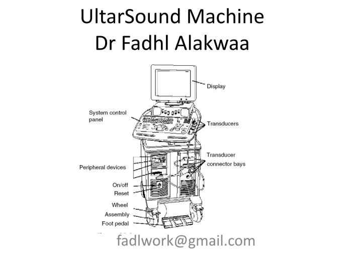
UltarSound MachineDr FadhlAlakwaa fadlwork@gmail.com
What are the first things to account when purchasing new US equipment • Clinical application • Operation Modes • Transducers • OTHERS • DISOM & STORAGE • PRINTER • NETWORKING
EXCELLENT RESOURCES • Ultrasound Machine Comparison: An Evaluation of Ergonomic Design, Data Management, Ease of Use, and Image Quality • http://www.compareultrasound.com/ • Objective measurements of image quality • Ultrasound Equipment Evaluation Project,
CLINICAL APPLICATIONS • Breast: Imaging of female (usually) breasts • Cardiac: Imaging of the heart • Gynecologic: Imaging of the female reproductive organs • Radiology: Imaging of the internal organs of the abdomen • Obstetrics (sometimes combined with Gynecologic as in OB/GYN): Imaging of fetuses in vivo • Pediatrics: Imaging of children • Vascular: Imaging of the (usually peripheral as in peripheral vascular) arteries and veins of the vascular system (called ‘‘cardiovascular’’ when combined with heart imaging)
(Note that ‘‘intra’’ (from Latin) means into or inside, ‘‘trans’’ means through or across, and ‘‘endo’’ means within.) • Endovaginal: Imaging the female pelvis using the vagina as an acoustic window
Intracardiac: Imaging from within the heart • Intraoperative: Imaging during a surgical procedure • Intravascular: Imaging of the interior of arteries and veins from transducers inserted in them • Laproscopic: Imaging carried out to guide and evaluate laparoscopic surgery made through small incisions • Musculoskeletal: Imaging of muscles, tendons, and ligaments
Small parts: High-resolution imaging applied to superficial tissues, musculature, and vessels near the skin surface • Transcranial: Imaging through the skull (usually through windows such as the temple or eye) of the brain and its associated vasculature • Transesophageal: Imaging of internal organs (especially the heart) from specially designed probes made to go inside the esophagus • Transorbital: Imaging of the eye or through the eye as an acoustic window • Transrectal: Imaging of the pelvis using the rectum as an acoustic window • Transthoracic: External imaging from the surface of the chest
What do you need to know to be professional in US? • Advantage of US OVER other modalities • US development • US physics • Ultrasound Terminology • US clinical applications • US components • US Transducer types • US modes • US specifications
What is Ultrasound machine? • Ultrasound or ultrasonography is a medical imaging technique that uses high frequency sound waves and their echoes. • But what is the ultrasound waves?
Spectrumofsound Example Frequency range Hz Description Infrasound 0 - 20 Earth quake 20 - 20.000 Audible sound Speech, music > 20.000 Ultrasound Bat, Quartz crystal Medical ultrasound frequency is 1Mhz-10Mhz الموجات الفوق صوتية نوعيين طولية وعرضية Krautkramer NDT Ultrasonic Systems
Sound propagation Longitudinal wave Direction of propagation Direction of oscillation Krautkramer NDT Ultrasonic Systems
Direction of propagation Sound propagation Transverse wave Direction of oscillation Krautkramer NDT Ultrasonic Systems
330 m/s AirWaterSteel, longSteel, trans 1480 m/s 5920 m/s 3250 m/s Wave propagation Longitudinal waves propagate in all kind of materials. Transverse waves only propagate in solid bodies. Due to the different type of oscillation, transverse wavestravel at lower speeds. Sound velocity mainly depends on the density and E-modulus of the material. Krautkramer NDT Ultrasonic Systems
Difference between EM and sound? • Material through which wave moves • Medium not required for all wave types • no medium required for electromagnetic waves • radio • x-rays • infrared • ultraviolet • medium is required for sound • sound does not travel through vacuum Talk louder! I can’t hear you.
How to produce sound wave? • By applying voltage on some material face like: • Quartz • PZT
+ Piezoelectric Effect Battery Piezoelectrical Crystal (Quartz) Krautkramer NDT Ultrasonic Systems
+ Piezoelectric Effect The crystal gets thicker, due to a distortion of the crystal lattice Krautkramer NDT Ultrasonic Systems
+ Piezoelectric Effect The effect inverses with polarity change Krautkramer NDT Ultrasonic Systems
Piezoelectric Effect Sound wave withfrequency f U(f) An alternating voltage generates crystal oscillations at the frequency f Krautkramer NDT Ultrasonic Systems
Piezoelectric Effect Short pulse ( < 1 µs ) A short voltage pulse generates an oscillation at the crystal‘s resonant frequency f0 OPERATING FREQUNCY Krautkramer NDT Ultrasonic Systems
How to receive sound waves? A sound wave hitting a piezoelectric crystal, induces crystal vibration which then causes electrical voltages at the crystal surfaces. Electrical energy Piezoelectrical crystal Ultrasonic wave Krautkramer NDT Ultrasonic Systems
Focus Angle of divergence Crystal Accoustical axis 6 D0 N Near field Far field Sound field Krautkramer NDT Ultrasonic Systems
Transducer array • Transducer = ARRAY OF PIEZOELECTRICAL ELEMENTS. Typically 128 to 512 • SPECFICATION: • Material • ARRAY LENGHT • Frequency rang • resolution • Depth CM • Type • LINEAR ARRAY • PHASED ARRAY
Ultrasound Display • One sound pulse produces • one image scan line • one series of gray shade dots in a line • Multiple pulses • two dimensional image obtained by moving direction in which sound transmitted
Real-time Scanning • Each pulse generates one line • Except for multiple focal zones • one frame consists of many individual scan lines lines frames PRF (Hz) = ------------ X -------------- frame sec. One pulse = one line
Linear, Curved linear array, Phased array/sectorEndocavitary, Intraoperative
Transducer Arrays • Virtually all commercial transducers are arrays • Multiple small elements in single housing • Allows sound beam to be electronically • Focused • Steered • Shaped
Electronic Scanning • Transducer Arrays • Multiple small transducers • Activated in groups
Electrical Scanning • Performed with transducer arrays • multiple elements inside transducer assembly arranged in either • a line (linear array) • concentric circles (annular array) Curvilinear Array Linear Array
Linear Array Scanning • Two techniques for activating groups of linear transducers • Switched Arrays • activate all elements in group at same time • Phased Arrays • Activate group elements at slightly different times • impose timing delays between activations of elements in group
Linear Switched Arrays • Elements energized as groups • group acts like one large transducer • Groups moved up & down through elements • same effect as manually translating • very fast scanning possible (several times per second) • results in real time image
Linear Phased Array • Groups of elements energized • same as with switched arrays • voltage pulse applied to all elements of a groupBUT • elements not all pulsed at same time 1 2
Linear Phased Array • timing variations allow beam to be • shaped • steered • focused Above arrows indicate timing variations. By activating bottom element first & top last, beam directed upward Beam steered upward
Linear Phased Array Above arrows indicate timing variations. By activating top element first & bottom last, beam directed downward Beam steered downward By changing timing variations between pulses, beam can be scanned from top to bottom
Linear Phased Array Focus Above arrows indicate timing variations. By activating top & bottom elements earlier than center ones, beam is focused Beam is focused
Linear Phased Array Focus Focal point can be moved toward or away from transducer by altering timing variations between outer elements & center
Linear Phased Array Focus • Multiple focal zones accomplished by changing timing variations between pulses • Multiple pulses required • slows frame rate
Listening Mode • Listening direction can be steered & focused similarly to beam generation • appropriate timing variations applied to echoes received by various elements of a group • Dynamic Focusing • listening focus depth can be changed electronically between pulses by applying timing variations as above 2
1.5 Transducer • ~3 elements in elevation direction • All 3 elements can be combined for thick slice • 1 element can be selected for thin slice Elevation Direction
1.5 & 2D Transducers • Multiple elements in 2 directions • Can be steered & focused anywhere in 3D volume
Remember me to explain why we use the backing block and matching layer?
What we will use the returned or received ultrasound waves “echoes”? • NO ECHOES = NO IMAGING • WE WILL BACK TO THAT
Perpendicular Incidence • Sound beam travels perpendicular to boundary between two media 90o Incident Angle 1 2 Boundary between media
Oblique Incidence • Sound beam travel not perpendicular to boundary Oblique Incident Angle (not equal to 90o) 1 2 Boundary between media