Ethernet-driven control and data acquisition scheme for the Timepix-based TPC readout
180 likes | 356 Views
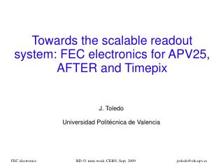
Ethernet-driven control and data acquisition scheme for the Timepix-based TPC readout. R.Degele , C.Kahra , U.Schäfer , S.Tapprogge , D.Wicke , M.Zamrowski Univ. Mainz . TPC readout chain. TPC to be read out by one or several pixel sensors (256*256 pixels)

Ethernet-driven control and data acquisition scheme for the Timepix-based TPC readout
E N D
Presentation Transcript
Ethernet-driven control and data acquisition scheme for the Timepix-based TPC readout R.Degele, C.Kahra, U.Schäfer, S.Tapprogge, D.Wicke, M.Zamrowski Univ. Mainz
TPC readout chain TPC to be read out by one or several pixel sensors (256*256 pixels) • Timepix chip bonded on a FR4 carrier • Amplifier • Discriminator • TDC • Time Over Threshold • Common stop • Serialiser (LVDS link) • Flat cable connection (ZIF) to adapter board • Trigger, test pulse, voltage monitor • Flat cable connection to Xilinx ML506 evaluation board • FPGA Virtex-5 (XC5VSX50-TFFG1136) • Deserialiser • Buffer • Ethernet / IP packet engine (UDP) • Ethernet link to computer
TPC readout chain TIMEPIX- ADAPTER- BOARD GEM Timepixchip cathode ML506 ETHERNET Ionizing particles
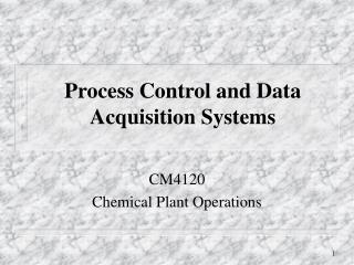
Lab test setup Programmer Flat cable Xilinx ML506 Adapter Ethernet to computer Flat cable Timepix
Timepix • 256*256 channel matrix • 55µm * 55µm pitch • Analogue input stage with per-pixel threshold adjust • Digital TDC w. 14-bit LFSR counters @ up to 100MHz • Several conversion modes incl. TOT and common stop • shutter input • No zero suppression • Serialisation of matrix data (~1Mbit) into LVDS output • Auxiliary controls: • Test pulse in • Diagnostics : analogue monitor for internal current sources (DAC_OUT)
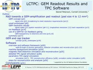
Timepix 10µm 20µm 55µm Pixel cell
Timepix – a few particularities • There exists a global threshold setting (THL, 14-bit) • Pixels can be threshold-corrected individually by a 4-bit value. • Range of threshold correction is set globally (THS) • Above global settings and other current source settings can be read back as analogue voltages via DAC_OUT pin for diagnostic purposes • Counters are 14-bit Linear Feedback Shift Registers = Pseudo Random Number Generators • Require linearisation so as to recover the time/amplitude information • Require special consideration if zero suppression or thresholding are to be done • Serial communication done by a simple clock/data/enable interface, through shift register
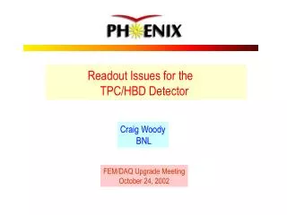
Adapter board Power supply S/N Connector toTimepix 3V Connector toXilinx ML506 ID -NUMBER 3V, 5V 7V 2V2 TIMEPIX-CONTROL TIMEPIX-DATA (LVDS) DAC-OUT DIGITAL ADC 4-Channel 24-Bit DAC-OUT CONTROL, CLK, ADDRESS Voltage Reference 2V5 TP_IN 5V TEST_IN • Testpulse generator control Trigger RJ45 (TLU) TRIGGER, BUSY, RESET, DATA CLOCK
Adapter board To ML506 Trigger To Timepix Test pulse in Power To ML506
FPGA module : Xilinx ML506 • Virtex-5 based : XC5VSX50-TFFG1136 • On-chip Ethernet MAC • On-chip 3Gb/s serial links : run at 1Gb/s for Ethernet • On-board Gigabit Ethernet phy chip (1000BASE-T) • 64 bit user I/O on 2.54mm headers • Nonvolatile configuration storage via SystemACE (CompactFlash card) • A lot of periphery, not currently used for Timepix readout
FPGA Firmware • VHDL description • Common clock for digitisation and data transfer, crystal based, frequency currently hard coded in VHDL • SerDes interface to the Timepix bit-serial port • Control and status registers, data stream pass-through • Network communication based on Xilinx-supplied Ethernet macro (TEMAC wrapper) • No embedded CPU • Minimalist network protocol stack • UDP only • No management protocols (ARP etc.) • Shutter operated under software control or in response to a trigger (TLU) with programmable delay and width • Timepix protocol not fully understood from documents modelled on MUROS2 readout scheme
Firmware : Data transport to computer Data transmission scheme to readout PC using UDP protocol: <ethernet><IP><UDP><control><data> • standard Ethernet/IP/UDP headers • 18-byte control field mapped to register file within the FPGA (control and status words) • Variable length data field carrying data to/from Timepix chip • Timepix matrix data not buffered on FPGA,data kept on Timepix while awaiting packet transmission • Data pulled by computer (handshake)
Control software • C++ • Currently command line interface only, no GUI • Base functionality: • Reset Timepix • Set current sources (write FSR) • Enable test pulse • Set Timepix matrix • Read out matrix • Operate shutter • Complex operations • Start a run : initialise matrix and read it out upon reception of a trigger, linearise data, write to file • Pixel calibration
Pixel calibration Intercalibrate all pixels so as to achieve a uniform noise level across the whole of the chip • Measure noise in TOT mode for a fixed period of time • Repeat the measurement for • All global threshold settings ( 0 to 16383) (THL) • All per-pixel threshold corrections (0 to 15) • A pre-set correction scale (THS, 0 to 255) • Calculate optimum per-pixel correction values Software status: Base functionality and run control done Pixel calibration s/w development under way To do: read back current source data (DAC_OUT)
Tests / Results • Timepix and readout wired up in the lab (Mainz) • Run with TPC in Bonn • Readout working at • Event rates up to 23 Hz @ 40MHz system clock ++ • Scaling to 33 Hz @ 100MHz clock • Readout rate of bare Timepix would be (100Mbit/s) / 1Mbit = 100Hz • FPGA code pipelined, packet overhead is low • FPGA currently polled by PC, i.e. handshake for each packet transmitted Bottleneck probably due to latency in Linux IP stack
Results: Some basic sanity checks ... • Noise @ threshold THL=290, common stop mode • 8000 test pulses, counter mode. 17*13 pixel clusters masked out Locally induced noise, “written” to Timepix sur-face with a pulser and an insulated wire Timepix pixel matrix 256*256
Results: muons in the TPC • Energy deposit (TOT mode) Muon tracks crossing the TPC at 8.9cm and 2.8cm distance to readout plane. Both deposited charge and drift time measured concurrently by operating every other pixel in TOT or common stop mode • X-Y-Zdrift view • (common stop mode)
Summary / Outlook • A readout system for a TPC, with Timepix-based digitisation, has been implemented on a Xilinx ML506 development board (Virtex-5) • Data path off the FPGA into the computer via Gbit Ethernet and UDP protocol • Readout rate currently up to 33 events per second • System successfully operated in the electronics lab and on a TPC • Plans: • Re-target to Virtex-6 • Increase event rate • Increase channel count • Consider zero-suppression on the FPGA • …