Download
1 / 24
240 likes | 331 Views
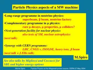
Bunched-Beam Phase Rotation for a Neutrino Factory. David Neuffer Fermilab. Outline. Introduction Study 2 scenario Induction linac phase rotation + 200 MHz buncher “High-frequency” Buncher and Rotation Concept 1-D simulation 3-D simulations – Simucool, ICOOL

E N D
Bunched-Beam Phase Rotationfor a Neutrino Factory David Neuffer Fermilab
Outline • Introduction • Study 2 scenario • Induction linac phase rotation + 200 MHz buncher • “High-frequency” Buncher and Rotation • Concept • 1-D simulation • 3-D simulations – Simucool, ICOOL • Mismatch into cooling channel • Toward “realistic” implementation • Elvira, Keuss Geant4 simulations • Cost guesstimates … • Future Studies • Variations • Matching, Optimization Study 3
Neutrino Factory Baseline Design • Feasible, but expensive • Find ways to reduce costs …
Study 2 system • Drift to develop Energy- phase correlation • Accelerate tail; decelerate head of beam (280m induction linacs (!)) • Bunch at 200 MHz • Inject into 200 MHz cooling system
Study 2 Scenario – induction linacs • Study II scenario uses • ~ 280m of induction • linacs to capture muons. • Cost is very high • Technology is difficult
Adiabatic buncher + Vernier Rotation • Drift (90m) • decay; beam develops correlation • Buncher(60m)(~333200MHz) • Forms beam into string of bunches • Rotation(~10m)(~200MHz) • Lines bunches into equal energies • Cooler(~100m long)(~200 MHz) • fixed frequency transverse cooling system Replaces Induction Linacs with medium-frequency rf (~200MHz) !
Longitudinal Motion (1-D simulations) Drift Bunch E rotate Cool System would capture both signs (+, -) !!
Buncher overview • Adiabatic buncher • Set T0, : • 125 MeV/c, 0.01 • In buncher: • Match torf=1.5m at end: • zero-phase with 1/ at integer intervals of : • Adiabatically increase rf gradient: rf : 0.901.5m
“Vernier” Rotation • At end of bunch, choose: • Fixed-energy particle T0 • Second reference bunch TN • Vernier offset • Example: • T0 = 125 MeV • Choose N= 10, =0.1 • T10 starts at 77.28 MeV • Along rotator, keep reference particles at (N + ) rf spacing • 10 = 36° at =0.1 • Bunch centroids change: • Use Erf = 10MV/m; LRt=8.74m • High gradient not needed … • Bunches rotate to ~equal energies. rf : 1.4851.517m in rotation; rf = ct/10 at end (rf 1.532m) Nonlinearities cancel: T(1/) ; Sin()
1-D 3-D Simulations (A. van Ginneken) • Initial examples are 1-D • Add transverse focusing (1.25T solenoid); initial beam from MARS simulations (Mokhov) of target production • Use Large statistics tracking code (SIMUCOOL, A. Van Ginneken) Reoptimize all parameters– • Drift to 76m, • Buncher parameters: • 384233 MHz • Linear ramp in voltage 0 to 6.5MV/m, 60m long • Rotator: • “vernier” frequency (20 + ) wavelengths between reference bunches (234220 MHz), 10MV/m, 0.16 • 30m long • Obtains ~0.4 /p
Bunching and Rotation Beam after ~200MHz rf rotation; Beam is formed into string of equal-energy bunches; matched to cooling rf acceptance Beam after drift plus adiabatic buncher – Beam is formed into string of ~ 200MHz bunches System would capture both signs (+, -) !!
Next step: match into cooling channel ! • Need to design a new cooling channel, matched to bunched/rotated beam • Do not (yet) have redesigned/matched cooling channel • Use (for initial tries): • ICOOL beam from end of AVG simulations • Study 2 cooling channel • Direct transfer of beam (no matching section)
Results (~ICOOL) • In first ~10m, 40% of ’s from buncher are lost, 0.020m 0.012m • Remaining ’s continue down channel and are cooled and scraped, ~0.0022m, similar to Study 2 simulation. • Best energy, phase gives ~0.22 ’s /24 GeV p • Study 2 baseline ICOOL results is ~0.23 ’s/p GeV m
Compare with Study II (Capture + Cooling) x: –20 to 100m; y: 0 to 400 MeV
Caveats: Not properly matched • This is not the way to design a neutrino factory • Not properly matched in phase space • Cooling channel acceptance is too small (add precooler ?) • Correlation factors “wrong” • “Cooling” channel collimates as much as it cools …
To do • Move to more realistic models • Continuous changes in rf frequencies to stepped changes … • 3-D fields (not solenoid + sinusoidal rf) • Match into realistic cooling channels … • Estimate/Optimize Cost/performance
GEANT4 simulations (D. Elvira) • Fully “realistic” transverse and longitudinal fields • Magnetic fields formed by current coils • Rf fields from pillbox cavities (within solenoidal coils) • Studied varying number of different rf cavities in Buncher • (60 (1/m) to 20 to 10) … 20 was “better”, 10 only a bit worse • Simulations of -δE rotation • Will (?) extend simulations + optimization through cooling channel
10-frequencyBuncher Only 10 frequencies and voltages. (10 equidistant linacs made of 6 cells) 62.2% of the particles survive at the end of the buncher.
GEANT4 Phase Rotation (D. Elvira, N. Keuss) Phase rotation successful Agrees with simplified models/simulations NOT optimized; Need to continue with simulation into cooling channel
Hardware/Cost For Buncher/Rotator • Rf requirements: • Buncher: ~300~210 MHz; 0.14.8MV/m (60m) (~10 frequencies; ~10MHz intervals) • Rotator: ~210200 MHz; 10MV/m (~10m) • Transverse focussing • B=1.25T solenoidal focusing;R=0.30m transport • System Replaces Study 2: (Decay(20m, 5M$); Induction Linacs(350m, 320M$); Buncher(50m,70M$)) • with: • Drift (100m); Buncher (60m);Rf Rotator (10m) • (Rf =30M$ (Moretti); magnets =40M$(M. Green);conv. fac.,misc.20M$) (400M$ ?? 100M$ ) • needs more R&D …
Variations/ Optimizations … • Many possible variations and optimizations • But possible variations will be reduced after design/construction • Shorter bunch trains ?? For ring Coolers ?? • Can do this with shorter buncher/rotator • ( with same total rf voltage …) • Other frequencies ?? • 200 MHz(FNAL) 88 MHz ?? (CERN) ??? (JNF) • Cost/performance optima for neutrino factory (Study 3?) • Collider ??both signs (+, -) ! • Graduate students (MSU) (Alexiy Poklonskiy, Pavel Snopok) will study these variations; optimizations; • First task would be putting buncher into MSU code COSY
Summary • High-frequency Buncher and E Rotator simpler and cheaper than induction linac system • Performance as good (or almost …) as study 2, But • System will capture both signs (+, -) ! (Twice as good ??) • Method should (?) be baseline capture and phase-energy rotation for anyneutrino factory … To do: • Complete simulations with matched cooling channel! • Optimizations, Scenario reoptimization