Download
1 / 24
240 likes | 270 Views
Explore FlowLab modeling software for fluid mechanics education, simulation of pipe flow, heat transfer concepts, and real-world applications. Instructions, validation with analytical data, parameters setup guidance included.

E N D
Simulation of Pipe Flow Using FlowLab 1.1 (PreLab 1) Tao Xing and Fred Stern IIHR—Hydroscience & Engineering 100 Hydraulics Laboratories The University of Iowa 57:020 Mechanics of Fluids & Transport Processes http://css.engineering.uiowa.edu/~fluids/ October 21, 2003
Outline • What is FlowLab?* • What can FlowLab do?* • Tutorial for running FlowLab • EFD data format for FlowLab • Instructions on setting up parameters • Other FlowLab functions • Validation using AFD * From http://www.flowlab.fluent.com
What is FlowLab? • Computational fluid dynamics (CFD) software package designed to help teach fluid mechanics and transport phenomena • Based on ready-to-use exercises, FlowLab eliminates the long learning curve associated with general fluid flow modeling packages • FlowLab exercises are templates created from FLUENT and GAMBIT parameterized files • FlowLab templates available in 57:020 are pipe (CFD Lab1) and airfoil flows(CFD Lab2)
What can FlowLab do? • Reinforce basic concepts of fluid mechanics and heat/mass transfer using computer simulation • Use computing exercises to augment and complement existing laboratory-based curriculum • Expand the learning experience with real-world applications of fluid flow and heat/mass transfer • Expose students to CFD and CFD concepts -- an increasingly important skill in the job market
FlowLab interface CFD process 1~6 CFD process: step 1, Geometry Sketch window Global control buttons
CFD process: Step 1, Geometry Units, SI recommended Reset values to default ones Create Geometry Go to CFD process, step 2 You are required to input the minimum parameters to create the geometry
CFD process: Step 1, Geometry Geometry Created
CFD process: Step 2, Physics With heat transfer?
CFD process: Step 2, Physics(BCs details) When inlet velocity has a distribution
CFD process, step 4, Solve Stop the calculation to see intermediate results Calculation will stop if either of the two parameters satisfied Time history of residuals
Reports (examples of results) Try to determine the location for the flow to become fully developed
CFD Process, step 6, Post-Processing (Contours) Choose the contour variables
CFD Process, step 6, Post-Processing (vectors) Choose appropriate scale to view velocity vectors
EFD data format for FlowLab (title "Velocity Magnitude") (labels "Position" "Velocity Magnitude") ((xy/key/label "experimental") 0.00 68.25937 0.005 67.16533 0.01 64.64357 0.015 60.6072 0.02 55.80557 0.021 54.26333 0.022 52.45669 0.023 49.98777 0.024 47.58417 0.025 42.3885 ) Replaced with your own EFD data! Axial velocity profile
Instructions for setting up parameters • Appropriate set-up of parameters can save both time and efforts to get the correct results • Iteration number usually set to a large value (eg. 10000). • The convergence limit for “single-precision” can be larger than 10^-4, but not lower than 10^-5. No restrictions for “double-precision”. • The default scale for plotting velocity vectors is very large, reduce that value to 0.003 or so for a better view
Other functions Fit the view to full size Align the geometry with coordinates
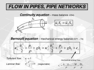
Validation with AFD • The pipe template will be validated using the analytical data for fully developed laminar flows in pipes • Parameters: Pipe radius: R=0.02647 m Pipe length: L=9.144 m Inlet velocity: u=0.2 m/s (Re=610) Using Medium mesh and double precision • Use the equation above to calculate the analytical velocity distributions and save that data to a *.txt file with the format of FlowLab requires. • Questions: Will the change of the outlet gauge pressure affect the axial velocity distribution? Why?