Download
1 / 44
450 likes | 526 Views
STEADY-STATE POWER ANALYSIS. LEARNING GOALS. Instantaneous Power For the special case of steady state sinusoidal signals. Average Power Power absorbed or supplied during one cycle. Maximum Average Power Transfer When the circuit is in sinusoidal steady state.

E N D
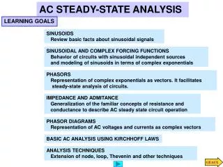
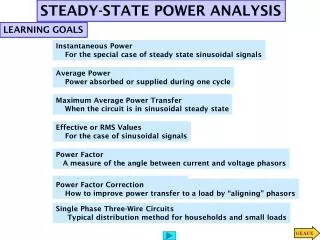
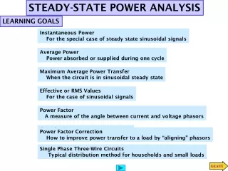
STEADY-STATE POWER ANALYSIS LEARNING GOALS Instantaneous Power For the special case of steady state sinusoidal signals Average Power Power absorbed or supplied during one cycle Maximum Average Power Transfer When the circuit is in sinusoidal steady state Effective or RMS Values For the case of sinusoidal signals Power Factor A measure of the angle between current and voltage phasors Complex Power Measure of power using phasors Power Factor Correction How to improve power transfer to a load by “aligning” phasors Single Phase Three-Wire Circuits Typical distribution method for households and small loads
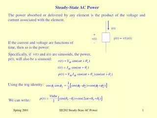
LEARNING EXAMPLE constant Twice the frequency INSTANTANEOUS POWER
LEARNING EXAMPLE Find the average power absorbed by impedance If voltage and current are in phase Purely resistive If voltage and current are in quadrature Purely inductive or capacitive AVERAGE POWER For sinusoidal (and other periodic signals) we compute averages over one period It does not matter who leads Since inductor does not absorb power one can use voltages and currents across the resistive part
If voltage and current are in phase Determine the average power absorbed by each resistor, the total average power absorbed and the average power supplied by the source LEARNING EXAMPLE Inductors and capacitors do not absorb power in the average Verification
LEARNING EXTENSION Find average power absorbed by each resistor
Method 1. Method 2: LEARNING EXTENSION Find the AVERAGE power absorbed by each PASSIVE component and the total power supplied by the source Power supplied by source
Passive sign convention LEARNING EXAMPLE Determine average power absorbed or supplied by each element To determine power absorbed/supplied by sources we need the currents I1, I2
Alternative Procedure Determine average power absorbed/supplied by each element LEARNING EXTENSION Check: Power supplied =power absorbed
Determine average power absorbed/supplied by each element LEARNING EXTENSION
LEARNING EXAMPLE Remove the load and determine the Thevenin equivalent of remaining circuit We are asked for the value of the power. We need the Thevenin voltage
Circuit with dependent sources! KVL KVL LEARNING EXAMPLE Next: the short circuit current ...
Substitute and rearrange LEARNING EXAMPLE (continued)... Original circuit
KVL LEARNING EXTENSION
If the current is sinusoidal the average power is known to be EFFECTIVE OR RMS VALUES The effective value is the equivalent DC value that supplies the same average power Definition is valid for ANY periodic signal with period T
One period The two integrals have the same value Compute the rms value of the voltage waveform LEARNING EXAMPLE
Compute the rms value of the voltage waveform and use it to determine the average power supplied to the resistor LEARNING EXAMPLE
LEARNING EXTENSION Compute rms value of the voltage waveform
LEARNING EXTENSION Compute the rms value for the current waveforms and use them to determine average power supplied to the resistor
Losses can be reduced by 2kW! Find the power supplied by the power company. Determine how it changes if the power factor is changed to 0.9 LEARNING EXAMPLE Current lags the voltage Power company If pf=0.9 If pf=0.9 Examine also the generated voltage
LEARNING EXTENSION Determine the power savings if the power factor can be increased to 0.94
inductive capacitive Another useful form Active Power Reactive Power COMPLEX POWER The units of apparent and reactive power are Volt-Ampere
inductive capacitive lagging LEARNING EXAMPLE Determine the voltage and power factor at the input to the line inductive
Passive sign convention. Power received by A Compute the average power flow between networks Determine which is the source LEARNING EXAMPLE A supplies 7.2kW average power to B
inductive capacitive LEARNING EXTENSION Determine real and reactive power losses and real and reactive power supplied Balance of power
The phasor diagram helps in visualizing the relationship between voltage and current lagging LEARNING EXTENSION Determine line voltage and power factor at the supply end
Simple approach to power factor correction POWER FACTOR CORRECTION Low power factors increase losses and are penalized by energy companies Typical industrial loads are inductive
LEARNING EXAMPLE Roto-molding process
Determine the capacitor necessary to increase the power factor to 0.94 LEARNING EXTENSION
General balanced case Basic circuit. SINGLE-PHASE THREE-WIRE CIRCUITS Power circuit normally used for residencial supply Line-to-line used to supply major appliances (AC, dryer). Line-to-neutral for lights and small appliances An exercise in symmetry General case by source superposition Neutral current is zero Neutral current is zero
Assume all resistive Lights on Stereo on Determine energy use over a 24-hour period and the cost if the rate is $0.08/kWh LEARNING EXAMPLE Outline of verification
Typical residential circuit with ground and neutral SAFETY CONSIDERATIONS Average effect of 60Hz current from hand to hand and passing the heart Required voltage depends on contact, person and other factors Ground conductor is not needed for normal operation
LEARNING EXAMPLE Increased safety due to grounding When switched on the tool case is energized without the ground connector the user can be exposed to the full supply voltage! Conducting due to wet floor If case is grounded then the supply is shorted and the fuse acts to open the circuit More detailed numbers in a related case study
Wet skin Limbs trunk Suggested resistances for human body LEARNING EXAMPLE Ground prong removed Can cause ventricular fibrillation
LEARNING EXAMPLE Ground Fault Interrupter (GFI) In normal operating mode the two currents induce canceling magnetic fluxes No voltage is induced in the sensing coil
Circuit formed when boy in water touches boy holding grounded rail LEARNING EXAMPLE A ground fault scenario While boy is alone in the pool there is no ground connection x Ground fault Vinyl lining (insulator)
New path created by the grounding Accidental grounding LEARNING EXAMPLE Only return path in normal operation Using suggested values of resistance the secondary path causes a dangerous current to flow through the body
720V/m One step applies 720 Volts to the operator LEARNING EXAMPLE A grounding accident After the boom touches the live line the operator jumps down and starts walking towards the pole 7200 V Ground is not a perfect conductor 10m
Car body is good conductor Tires are insulators Suggested resistances for human body LEARNING EXAMPLE A 7200V power line falls on the car and makes contact with it 7200V Wet Road Option 1. Driver opens door and steps down Option 2: Driver stays inside the car
CASE 1: 16-gauge wire CASE 2: 14-gauge wire LEARNING EXAMPLE Find the maximum cord length Minimum voltage for proper operation Working with RMS values the problem is formally the same as a DC problem
Circuit at start of AC unit. Current demand is very high AC off AC in normal operation LEARNING EXAMPLE Light dimming when AC starts Typical single-phase 3-wire installation
LEARNING BY DESIGN Analysis of single phase 3-wire circuit installations Steady-state Power Analysis Option 1 Option 2