Download
1 / 14
140 likes | 158 Views
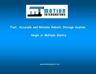
Introducing the 2.4XLSA X-L Band System by Orbital Systems, Ltd. Designed to address the limitations of existing pedestals, this system offers reliable and accurate reception of X and L band satellites and is built for operation in extreme climates. With a focus on preventing common failures and ensuring long life with minimal maintenance, this cost-effective solution provides reliable direct readout capabilities.

E N D
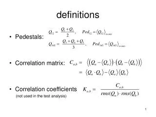
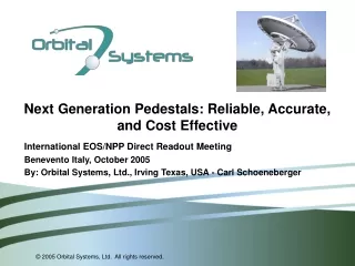
Next Generation Pedestals: Reliable, Accurate, and Cost Effective International EOS/NPP Direct Readout Meeting Benevento Italy, October 2005 By: Orbital Systems, Ltd., Irving Texas, USA - Carl Schoeneberger
Who is Orbital Systems, Ltd. ? • Founded in early 2004 • Common ownership with Quorum Communications • Common quality and customer service philosophy • Access to Quorum’s enormous knowledge of industry • Principals are all experts in their respective disciplines with many years of product development experience • Addressing the Pedestal and Systems markets • Initial product is 2.4m system for X-Band Terra, Aqua, Aura; L- Band NOAA-POES and Feng-Yun 1 series with future NPP and NPOESS options • In development with 1.8m T&C and SARSAT system • Tactical systems
Some existing 2.4m pedestals were not designed for X Band operation Many designs can’t handle wide temperature extremes or had wind torque limitations requiring use of expensive radomes Absolute pointing accuracy limitations were sometimes solved with complex mechanical tracking feeds Many designs are prone to common failures Corrosion damage Brake faults Sensor / Limit switch / Index failures Internal cable wrap-up destruction Most designs are not engineered for low maintenance Systems need frequent, and often expensive, attention Legacy Pedestals and systems are just too expensive Challenges of current technolgy:
Announcing the 2.4XLSA X-L Band System • Traditional Elevation over Azimuth design • Track X and L band satellites with no “keyhole” effect • Standard system includes pedestal, reflector, X-L concentric feed, X Band downconverter and receiver and L Band block converter and receiver • Base system receives Terra, Aqua, Aura, NOAA-POES and Feng-Yun 1 • Future options for reception of X-Band NPP and NPOESS and L-Band METOP and NPOESS • On axis feed permits simultaneous reception of X and L Band • Built in GPS time reference • Typical G/T: X-Band 24 dB/K, L-Band 9 dB/K • 2.4m heavy duty reflector with high surface accuracy • Rugged construction and designed for operation in extreme climates • Designed for long life with minimal maintenance • Fiber option – remote control and reception up to 20km away
Designed in speed to eliminate the “keyhole”: • Speeds of almost 60 degrees per second are necessary • High speed, high torque brushless servo-motor technology delivers full torque even when stopped, allowing for accurate pointing during heavy wind loading and gusts • Motor, feedback and brake all sealed together to IP 65
Designed in high torque main gears: • Extra heavy duty gearing to withstand high wind and inertial loads. • Sealed gears are lubricated for greater than a 10 year operating life 24 / 7 • Gears are automatically heated by the controller to permit normal operation at temperatures down to – 40 C
Designed in High Accuracy: • High precision machining with critical component tolerances below .05mm using machines accurate to .01mm • Axis position feedback sensors that are accurate to ±.02 deg and directly coupled to output shafts eliminating gearing errors and providing absolute position data • The entire mechanical system is designed to be very stiff, including the reflector and reflector attachment
Prevent Corrosion, a major source of failure: • Construct the system of non-corrosive metals such as Aluminum and marine grade Stainless Steel • Use powder coating and hard anodizes to stop oxidation • Double coat external steel counterweights to prevent rust stains • Pressurize the pedestal AND the feed to keep moisture out and prevent common problems like rusting brakes, unreliable electrical connections, worn gears and failed system components
Extreme Temperatures and Environment: • Careful selection of all materials to ensure low and high temperature limits are met • Static seals made of silicone and dynamic seals made of PTFE (Teflon) will last indefinitely even in high UV and ozone conditions and will endure wide temperature extremes • Use lubricants designed for wide temperature range and long life. To reach lowest operating temperatures heat gearcases when needed. • Use powder coatings that block UV, do not react to ozone, reject fungal growth, and reflect heat
Monitoring and Safety: • Monitor internal system conditions • Power supplies • Internal system temperature at pedestal and feed • Internal system relative humidity at pedestal and feed • Internal system pressure • Alert system operator to faults through status display • For safety provide external user controls for emergency stopping and maintenance at pedestal • Independently monitor and stop system when unsafe conditions such as excess speed or limit switch failures occur. Wiring is designed to fail safe. Internal controller design is segmented for safety reasons.
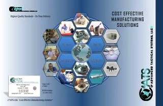
Cost Effectiveness: • Designed for long life with minimal maintenance to give the lowest lifetime cost of ownership • Vertically integrate design and manufacturing processes as much as possible, especially metalwork • Design in house using the latest CAD / CAM tools • Manufacture using automated CNC machines • Today Orbital Systems manufactures about 75% of the fabricated parts in the system and expects to achieve 95% by early next year • Design and manufacture control systems in house to exactly match the system needs • Use proven high quality RF components from Quorum Communications • Provide great customer service
Designing a typical mechanical part: • A short video follows to show the process of mechanical design using 3D CAD modeling methods, including the ability to visualize the interaction and fit of system components • The 3D model is processed with CAM software to design the automated machining processes • The part is then manufactured from raw aluminum bar stock on a vertical machining center • Associated parts are welded • The parts are sandblasted and powder coated • Last, it is shown mounted to the system
End Thank you for attending