Download
1 / 30
300 likes | 416 Views
A TIME OF FLIGHT DETECTOR FOR THERMAL NEUTRONS FROM RADIOTHERAPY LINACS. V. Conti, G.Bartesaghi, D.Bolognini, M.Prest, S.Scazzi, P.Cappelletti, M.Frigerio, S.Gelosa, A.Monti, A.Ostinelli, G.Giannini, E.Vallazza, A.Mozzanica. OUTLINE.

E N D
A TIME OF FLIGHT DETECTOR FOR THERMAL NEUTRONS FROM RADIOTHERAPY LINACS V. Conti, G.Bartesaghi, D.Bolognini, M.Prest, S.Scazzi, P.Cappelletti, M.Frigerio, S.Gelosa, A.Monti, A.Ostinelli, G.Giannini, E.Vallazza, A.Mozzanica
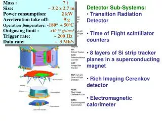
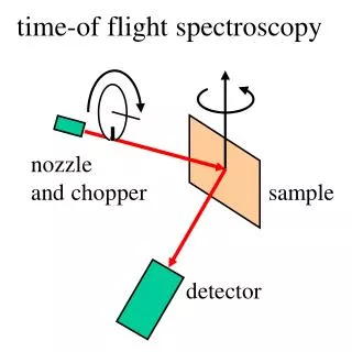
OUTLINE • The Boron Neutron Capture Therapy and its future in a hospital environment • A novel TOF detector : description and comparison with standard neutron detectors • Spectra and flux measurements with a Clinac 2100 • Simulation developments and comparison with data • Conclusion
RADIOTHERAPY The radiotherapy goal local control of the primary tumour Ideal situation : a large amount of energy deposited in the tumour volume and none in the surrounding healthy tissue Radiotherapy beams Photonsare useful to treat deep-seated tumours that is tumours located several cm below the skin surface Electronsfor superficial or semideep cancers DEPTH IN WATER (cm)
Although the percentage of survival is increased in the years, some tumours have a very low five-year survival probability
For localized tumours Hadron therapy Hadron radiation : Negative pions, protons and light ions (e.g. helium, carbon, neon, silicon and argon nuclei) BRAGG PEAK The dose increases with penetration depth from a low dose at the entrance to a sharp maximum at the end of the particle range Depth in water (cm)
HADRON THERAPY ADVANTAGE PROTON X-RAYS Extended tumours (liver, stomach or lung) but this treatment cannot be used for some kinds of tumour like Radio-resistant ones (melanoma) Tumours surrounded by vital organs (brain)
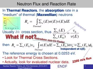
Four years after the discovery of neutrons in 1932 by Chadwick, Locker introduced the concept of BNCT The BNCT : Boron Neutron Capture therapy The BCNT is an oncology radiotherapy treatment that exploits the capture of thermal neutrons by 10B and the following emission of an α particle and a nucleus of 7Li
specific drugs (BSH or BPA) are being developed for this purpose boron is delivered mainly in the tumoral cells Irradiating tumor cells with a thermal neutron beam thus producing heavy charged particles releasing their whole energy in the cell High damage only in the target cells 10B tumor cell healthy cell
The BNCT requires: • a high thermal neutron flux (> 5x10⁸ n cm-2 s-1) • with a low energy neutron spectrum (neutron energy < 10 keV) Up to now such a beam is produced only in nuclear reactors a reactor would be too expensive and too dangerous to be put inside a hospital to develop a neutron source that can be used inside a hospital for BNCT treatments AN IDEA PHONES PROJECT
PhoNeS (PHOton NEutron Source) The aim of the PhoNeS project is to provide a competitive thermal neutron source using clinac radiotherapy Linacs, maximizing with a dedicated photo-neutron converter the neutrons produced by Giant Dipole Resonance (GDR) by a high energy photon beam (> 8 MeV) Accelerator head (Clinac 1800, 2100) photo-neutron converter (PhoNeS)
Giant Dipole Resonance • high energy photons hit a high Z target • fast neutrons are produced by GDR • neutrons are slowed down by a moderating material • neutron capture inside the device should be kept low • with as low as possible gamma field To obtain a Photon Neutron Source useful for medical purposes the following requirements have to be fulfilled: • a thermal neutron flux greater than 108 n cm-2 s-1 • a fast neutron and gamma dose per thermal neutron lower than 2x10-12 Sv cm2 n-1
Different prototypes and simulation have been developed to optimize the following parameters: Photoconverter lead thickness Moderator shape and thickness Box of moderator material (D2O)
MCNP-4B GN code Simulation WITH and WITHOUT PhoNeS prototype without PhoNeS with PhoNeS 76 % slow 34 % slow
In this framework a development of neutron detection methods to evaluate neutron and gamma doses is of primary importance COMMERCIAL NEUTRON DETECTORS: TLD • passive detector, it integrates the flux in a certain energy range over the whole measurement duration • not real time, it needs a long calibration procedure, an annhealing cycle before the use and after the readout • also sensitive to photons • high dynamic range BUBBLE DOSIMETERS • integrated measurement over time and energy • not real time; they can be used only with low doses; the counting of the bubbles can introduce large systematic errors • poor spatial resolution
MATERIAL ACTIVATION • integrated measurement over time and energy • a Ge or NaI detector nearby is needed • Usually one sample per time. Almost real time BF3 COUNTERS • real time readout • not tissue equivalent • geometry constraints
BEAM TIME STRUCTURE Electrons (as well as secondary photons) are emitted in a 3-5 µs wide bunch at a 150-300 Hz repetition rate (dose rate dependent) It means up to tens ms “empty” time between two following bunches In this time interval there are no more electrons or photons in the environment, only thermal neutrons survive a 0.025 eV neutron has a speed of 2.2 mm/µs
We are developing a real time neutron detector made of a scintillator coupled to a dedicated readout electronics Plastic scintillators are low cost and flexible detectors, historically used for fast neutrons but can be employed also for slow ones in this particular configuration of the beam For slow neutrons we can take advantage of the neutron capture by the hydrogen nuclei detecting the 2.2 MeV γ emitted in the reaction n + H D + γ (2.2 MeV)
THE FIRST DETECTOR A polystyrene plastic scintillator 2x2x1 cm3 Two P30CW5 photomultipliers by Electron Tubes with integrated high voltage power supply facing the two opposite sides of the scintillator to avoid dark counts and improve reliability The detector assembly
Our detection system should be able to return the number of captured neutrons and their arrival time Signals on the oscilloscope The read out electronics The signals from the scintillator are digitized by a NIM discriminator, threshold 30 mV The coincidence between the two PMs is shifted to LVDS and then sent to sampler sampling the discriminated signal with a 12.5MHz clock
This is an output example: each “1” corresponds to an impinging neutron For each experimental condition several bunches have been collected, obtaining a time arrival profile
WE HAVE TWO GOALS: TO MEASURE The neutron energy spectrum The neutron number
The comparison between the Al sample activation and the real time detector measurements in the scan along a diagonal from the accelerator head Measurement setup in S.Anna Hospital (Como, Italy)
This detector can be used to measure the energy spectrum The TOF spectrum has been fitted with a double exponential and the result is : Two different slopes: • 135 µs • 1.567 ms These constants represent the contribution of a slower and a faster part of the neutron spectrum. is it true?
the slow constant from the accelerator head material (lead) • the fast constant from a plastic material in the room Scan of PMMA Accelerator head rotated of 90° detector PMMA layer
From the TOF of each point …. The fast component is affected by the PMMA, since More PMMA=more thermalization The slow component doesn’t feel the effect of PMMA Ratio fast/slow
THE SECOND PROTOTYPE using a boron loaded plastic scintillator to evaluate an α and 7Li contributions BC-454(Bicron) a boron loaded plastic scintillator diameter = 2 cm thickness=0.5cm P30CW5 photomultiplier by Electron Tubes The assembled detector
Comparison of the scintillator data with the activation method and the simulation data DETECTOR DOSIMETER It counts the photons produced by the neutrons in the scintillator plus in all surrounding materials
the neutron energy spectrum is extracted from the simulation TOF The TOF simulation comparison with data This is a very important result for a BNCT treatment you need the information on the spectrum
CONCLUSION • BNCT in hospitals? … a dream becoming reality … • A real time detector made of standard plastic scintillator that is both a relative DOSIMETER and a SPECTROMETER • Can be used as a dosimeter at reactors? • Flux measurement = real time equivalent of attenuation Boron doped scintillating fibers or very thin scintillators that will allow to disentangle the contribution due to the photons produced by neutron capture in the surrounding materials. OUTLOOKS • Absolute dose computation both with Linac and reactors • Fiber system development • Measurements with Phones with different Linacs
A TIME OF FLIGHT DETECTOR FOR THERMAL NEUTRONS FROM RADIOTHERAPY LINACS V. Conti, G.Bartesaghi, D.Bolognini, M.Prest, S.Scazzi, P.Cappelletti, M.Frigerio, S.Gelosa, A.Monti, A.Ostinelli, G.Giannini, E.Vallazza, A.Mozzanica