Download
1 / 26
260 likes | 384 Views
Coordinate Measurement in 2-D and 3-D Geometries using FSI. ATLAS Group, University of Oxford S. M. Gibson, P. A. Coe, A. Mitra, D. F. Howell, R. B. Nickerson. Overview. Motivation – the alignment of ATLAS Demonstration system Square Grid Tetrahedral Grid Grid simulations Future Work.

E N D
Coordinate Measurement in 2-D and 3-D Geometries using FSI ATLAS Group, University of OxfordS. M. Gibson, P. A. Coe, A. Mitra, D. F. Howell, R. B. Nickerson Overview • Motivation – the alignment of ATLAS • Demonstration system • Square Grid • Tetrahedral Grid • Grid simulations • Future Work S. M. Gibson, P. A. Coe, Photon02, 5th September 2002
ATLASA Large Particle Detector for theLarge Hadron Collider S. M. Gibson, P. A. Coe, Photon02, 5th September 2002
Motivation – the alignment of ATLAS What is alignment? The procedure in which the positions of the detector elements are determined Inner Detector Geodetic Grid Physics requires 3-D shape variations to be measured to ~10 mm ATLAS = A Toroidal LHC ApparatuS LHC = Large Hadron Collider S. M. Gibson, P. A. Coe, Photon02, 5th September 2002
Requirements for ATLAS • Each arm of the geodetic grid must be measured to ~1 mm. • ~800 such 1-D length measurements to be made simultaneously. • Minimal mass components within the inner detector. • Radiation hard. • No maintenance for 10 years. S. M. Gibson, P. A. Coe, Photon02, 5th September 2002
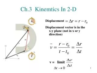
TUNABLE LASER sweep n IREF IMEASURED n2 n2 n1 n1 n n FSI Length Measurement DETECTOR M1 M2 To interferometer with OPD to be measured Reference Interferometer with fixed OPD DQ = [2p/c]DDn DF = [2p/c]LDn Ratio of phase change = Ratio of OPDs S. M. Gibson, P. A. Coe, Photon02, 5th September 2002
jewels support structure delivery fibre variable path quill fixed path return fibre beam splitter Interferometers inside ATLAS • Each line of the alignment grid inside ATLAS will consist of a quill (two optical fibres & beam splitter) and a retro-reflector. S. M. Gibson, P. A. Coe, Photon02, 5th September 2002
Splitter Tree and APD box Fibres Power Square Grid Demonstration System S. M. Gibson, P. A. Coe, Photon02, 5th September 2002
Demonstration system: Square Grid • 6 simultaneous length measurements made between four corners of the square. • +7th interferometer to measure stage position. • Displacements of one corner of the square can then be reconstructed. S. M. Gibson, P. A. Coe, Photon02, 5th September 2002
Overview of Measurements & Reconstruction • Simultaneous line of sight measurements • Calibration of jewel internal offsets • Check calibration by systematic removal of one line of sight in analysis • Check precision of reconstruction S. M. Gibson, P. A. Coe, Photon02, 5th September 2002
Square Grid S. M. Gibson, P. A. Coe, Photon02, 5th September 2002
Calibration of Jewel Internal Offsets S. M. Gibson, P. A. Coe, Photon02, 5th September 2002
Model Degrees of Freedom Node C is free in X and Y Node D is free in X and Y Node A defines the origin Node B defines the X axis S. M. Gibson, P. A. Coe, Photon02, 5th September 2002
Reconstruction S. M. Gibson, P. A. Coe, Photon02, 5th September 2002
Reconstruction of Jewel C Translation(Square Grid) Std Dev = 400 nm S. M. Gibson, P. A. Coe, Photon02, 5th September 2002
Correlation Plots for ‘all lines’ S. M. Gibson, P. A. Coe, Photon02, 5th September 2002
Tetrahedral Grid Square Grid Now sensitive to Z coordinate, allowing three dimensional coordinate reconstruction Jewel C raised up by 100mm S. M. Gibson, P. A. Coe, Photon02, 5th September 2002
Tetrahedral Grid Reconstruction Results S. M. Gibson, P. A. Coe, Photon02, 5th September 2002
Node C Three Dimensional Coordinate Reconstruction (Stationary Stage) S. M. Gibson, P. A. Coe, Photon02, 5th September 2002
Node C Three Dimensional Coordinate Reconstruction(Stage translated in X) S. M. Gibson, P. A. Coe, Photon02, 5th September 2002
Reconstruction of Jewel C Translation(Tetra Grid) S. M. Gibson, P. A. Coe, Photon02, 5th September 2002
Grids for ATLAS • The grid for ATLAS will contain eight hundred lines of sight in a complex geometry. • A quarter of the Barrel grid: • One of the two Endcap grids: • The error propagation through these grids has been simulated. S. M. Gibson, P. A. Coe, Photon02, 5th September 2002
0mm 35mm 70 Y Z X Simulgeoref1 model of Alignment Grid nodes (jewels) ASSUME: end flanges are rigid rings & central jewels constrained in rotation Barrel Grid Simulations Lines of sight for one quadrant of Alignment Grid FEA model of carbon fibre support structure S. M. Gibson, P. A. Coe, Photon02, 5th September 2002
Single Barrel Grid Simulation Results Result without radial lines to modules Central jewels constrained in rotation • NB: rigid end flanges assumed – currently repeating with increased number of degrees of freedom. • 1 micron precision assumed throughout. • Fixed inner barrel. S. M. Gibson, P. A. Coe, Photon02, 5th September 2002
Cross-check of Grid Simulations • Full barrel grid simulations should predict errors on all nodes of grid, for given measurement precisions. • Idea: • Take FEA model of perfect barrel • Extract grid line lengths • (add random errors to lengths) • Pass to reconstruction software for calibration of model • Distort FEA model eg, twist and/or multipole distortions • Extract new lengths • (add random errors to lengths) • Pass to reconstruction software • Calculate reconstructed node co-ordinates and compare with those in FEA model • Repeat later including interpolation software. S. M. Gibson, P. A. Coe, Photon02, 5th September 2002
Future Work • Continuing studies with the tetrahedral grid • More detailed full barrel grid simulations • Cross check of simulations using distorted FEA model • References ref1 used with kind permission of the author: • L. Brunel, ‘SIMULGEO: Simulation and reconstruction software for opto-geometrical systems’, CERN CMS Note 1998/079. S. M. Gibson, P. A. Coe, Photon02, 5th September 2002
Steve sends his apologies from Pylos… S. M. Gibson, P. A. Coe, Photon02, 5th September 2002