Download
1 / 26
290 likes | 608 Views
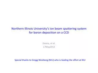
Northern Illinois University’s ion beam sputtering system for boron deposition on a CCD. Donna, et al. 17May2013. Special thanks to Gregg Westberg (NIU) who is leading the effort at NIU. Goal: Deposit 3 um of Boron-10 on the SiO 2 surface of a CCD.

E N D
Northern Illinois University’s ion beam sputtering systemfor boron deposition on a CCD Donna, et al. 17May2013 Special thanks to Gregg Westberg (NIU) who is leading the effort at NIU
Goal: Deposit 3 um of Boron-10 on the SiO2 surface of a CCD • We’d like to deposit 3 um of boron-10 on the SiO2 surface of a DES (DAMIC) CCD. • The SiO2is part of the anti-reflection (AR) coating. • The CCDs have a 2-layer AR coating: • 550 A ITO + 800 A SiO2 • Note: ITO = indium tin oxide • The indices are graded from silicon (n=3.5) to ITO (n=2) to SiO2 (n=1.46) to air (n=1.0). • That works better than a single-layer coating. nSi= 3.5 nITO= 2.0 nSiO2= 1.46 nair= 1.0 ITO (550 A) SiO2 (800 A) Boron-10 (3 um) Not to scale!!! n n n n
History • ANL (Greg Derylo) • e- beam evaporation • Boron peeled off • LBNL (conversation with Daniel Lee) • In the past, he deposited one micron thick B on SiO2 and Be substrates using an e-beam evaporation methodfor other projects at LBNL • e-beam evaporated boron films undergo stress cracking when the film is thicker than one micron. • Suggested RF magnetron sputtering
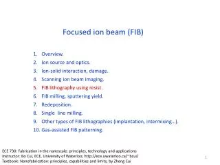
e- beam evaporation vs. ion beam sputtering B Ar e- beam evaporation e- beam heats the target (sublimation) Ion beam sputtering Sputtering deposition systems use high energy particles as a way of transferring kinetic energy to a target in order to remove material for deposition.
Characteristics and advantages of ion beam sputter deposition • Ion-beam sputtering (IBS) is a method in which the target is external to the ion source. • Kaufman source ions are generated by collisions with electrons that are confined by a magnetic field as in a magnetron. • They are then accelerated by the electric field emanating from a grid toward a target. • As the ions leave the source they are neutralized by electrons from a second external filament. • IBS has an advantage in that the energy and flux of ions can be controlled independently. • Since the flux that strikes the target is composed of neutral atoms, either insulating or conducting targets can be sputtered.
NIU’s Microelectronics Research and Development Laboratory (MRDL) • MRDL has sputtering capabilities • They are attempting to use ion beam sputtering to deposit boron on a CCD. • The yellow lighting is necessary for photolithography to prevent unwanted exposure of photoresist to light of shorter wavelengths. • All the blue is removed by filters or by use of special phosphors in the fluorescent tubes themselves. Location of Ion Beam Sputter deposition system (Class 100 cleanroom)
Ion beam sputter deposition system • This is the ion beam sputter deposition system NIU is modifying for the boron deposition. • It uses a Kaufman ion source to produce Ar ions which sputter the boron onto the CCD. • The CCD is attached to the water-cooled fixture designed by NIU and fabricated by FNAL • Base pressure 1 x 10⁻⁶Torr, operating pressure 5 x 10⁻⁴Torr. Ion source CCD Boron target
MRDL is making modifications to their ion beam sputtering system specifically for boron deposition on a CCD
Modifications to the ion beam sputtering system at MRDL • Modifications to the ion beam sputtering system specific for boron thin film deposition on a CCD • Neutral beam • Cooling • Fixture to support CCD • Modified boron target holder
Modifications to the ion beam sputtering system at MRDL • Modifications to the ion beam sputtering system specific for boron thin film deposition on a CCD • Neutral beam • Cooling • CCD fixture • Target holder
Neutral beam • The sputtering is done by a beam of neutral Ar produced by a Kaufman ion source • Hot filament emits e- • The e- ionize the Ar • Ar+ accelerated to accelerator grid • Screen focuses or collimates the Ar+ • Neutralizer adds e- to Ar+ • Ar coasts to B target (see next slides) • Neutral sputtering atoms prevent charging of the target. • Good for ESD-sensitive CCD Typical Kaufman ion source
Neutralizer • The ion beam deposition system has a neutralizer • The neutralizer converts the argon ions into neutral argon atoms before they strike the boron target. Grids Neutralizer
Modifications to the ion beam sputtering system at MRDL • Modifications to the ion beam sputtering system specific for boron thin film deposition on a CCD • Neutral beam • Cooling • CCD fixture • Target holder
Cooling • The CCD will be attached to the water-cooled fixture • The CCD foot was designed by Greg Derylo for DECam • The CCD will be wirebonded before boron deposition • Another view on next slide CCD foot Cooling lines
Cooling Cooling lines for CCD • Uses the fixture designed by NIU and fabricated by FNAL Ion gun CCD B Ar- Boron target
Modifications to the ion beam sputtering system at MRDL • Modifications to the ion beam sputtering system specific for boron thin film deposition on a CCD • Neutral beam • Cooling • CCD fixture • Target holder
CCD fixture Fixture to attach CCD. It will be possible to short the pins to reduce chance of ESD damage.
Modifications to the ion beam sputtering system at MRDL • Modifications to the ion beam sputtering system specific for boron thin film deposition on a CCD • Neutral beam • Cooling • CCD fixture • Target holder
Boron target • FNAL purchased the target with dimensions spec’d by NIU • 99.6% pure natural boron • 6.0 mm thick x 50.8 mm diameter • $900.00 (99.6% pure) Enriched boron is more expensive • Daniel Lee (LBNL) has a quote for a boron-10 target • > 92% boron-10 enriched • Size ? • $4000.00
Boron target Cooling lines for CCD • The boron target is held by an aluminum fixture • The Al extends beyond the edge of the boron targetwhich is evident in the photo • Gregg Westberg (MRDL) is worried that the Al is also being sputtered. • Gregg has designed a new target holder that will attach to the back side of the boron target to eliminate that problem. • He asked if FNAL can machine the new holder; he provided a drawing (next slide). • NIU is very short-staffed. Ion gun CCD B Ar- Boron target Aluminum fixture
Can deposited film be analyzed to see if it’s contaminated? Cooling lines for CCD • Question: Can either the AFM (atomic force microscope) or SEM (scanning electron microscope) at MRDL do elemental analysis? • Answer: EDS (Energy Dispersive Spectrometry) on the SEM if there is enough Al, pretty tough to detect B. AFM can't do elemental analysis. The high base pressure (1 x 10⁻⁶Torr) helps to minimize other contamination. Ion gun CCD B Ar- Boron target Aluminum fixture
First test of boron deposition • Deposited boron on 4-inch wafer that was covered with a “shadow mask” • The dark areas are boron • 500 Angstroms of boron (thickness measured with Dektakprofilometer). • Took ½ hour. • Need 3 microns! • Need to research how to speed up deposition rate.
What’s next? • Need to research how to speed up deposition rate. • Variables (may be others) • Ar energy • Ar flux • Target-CCD distance • Pressure • Change sputtering beam (next slide_ • Kr • Xe • ….
What’s next? • Argon is the most widely used working gas in sputtering due to the larger mass as compared to neon and helium (higher mass correlates to more energetic collisions with the target material) and the much lower cost of argon compared to xenon and krypton. • The efficiency of the inert gas for sputtering the target is defined by the sputter yield, S, which is a proportional to the ratio of the mass of the inert gas compared to the mass of the target: boron