Download
1 / 22
220 likes | 238 Views
Ultra-thin packaging technologies for CMOS pixel sensors: embedding in kapton foils. Wojciech Dulinski 1 , Serge Ferry 2 , Mathieu Goffe 1 , Rui de Oliveira 2 and Marc Winter 1 , 1 IPHC Strasbourg, France, 2 CERN, Geneve , Suisse. Outline Short status of MAPS development (at IPHC)

E N D
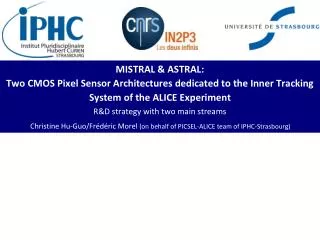
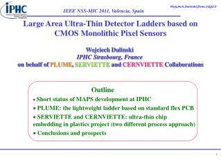
Ultra-thin packaging technologies for CMOS pixel sensors: embedding in kapton foils Wojciech Dulinski1, Serge Ferry2, Mathieu Goffe1, Rui de Oliveira2 and Marc Winter1, 1IPHC Strasbourg, France,2CERN, Geneve, Suisse • Outline • Short status of MAPS development (at IPHC) • - process evolution for monolithic radiation sensors: towards full CMOS and depleted substrate • - first application for particle physics: STAR µVertex • Chip embedding in plastics process for detector ladders construction • Some results and some problems • Conclusions and prospects
R.T. Monolithic Active Pixel Sensor: effective use of a thin epitaxial layer (10 – 20 µm) for MIP tracking May be extremely thin (~25 µm of silicon in total, ~0.027 % X0), flexible (!) and still fully efficient for MIP tracking!
Monolithic Active Pixel Sensor: CMOS process evolution ~2008 ~2010 ~2012 • Non-depleted, thick epi substrate: ~1012 n/cm2 • AMS 0.6 • AMS 0.35 • Semi-depleted, HR epi substrate >1013 n/cm2 • XFAB 0.6 • AMS 0.35 • Quadruple-well CMOS: both type of transistors admitted in the pixel array • TOWER 0.18 • Fully depleted, thick substrate >1014 n/cm2 ? • ESPROS 0.15 • TOWER 0.18
First real scale exercise of large system based on MAPS: new STAR Microvertex Detector: AMS 0.35 µm OPTO CMOS 400 sensors (2x2 cm2), 300 Mpixels Data taking (1/4 of detector) in 2013, full detector installation in 2014
New STAR Microvertex Detector Estimated 0.37% X0/ladder. Can we do better?
PLUME concept: double-sided ladder (ILC compatible) • 2x6 Mimosa26 sensors thinned down to 50 µm • Standard double-side kapton PCB: Cu conductor (20 µm/layer) • SiC foam (8%) for spacer between layers • Estimated 0.6 % X0/two sensor layers
Embedding principle Novel approach for ultra thin sensor packaging: use of a “standard” flex PCB process for chip embedding in plastic foilsThe goal: < 0.1 % of X0 per sensor layer (all included) • Gluing between two kapton foils • Opening vias using lithography • Metallization: Al (5-10 µm) • Lithography to pattern metal • Gluing of another kapton foil for deposition of second metal layer No wire bonding, excellent mechanical chip protection
Redistribution layer (vacuum deposited aluminum) : make the connection between silicon world and PCB world (from 50 µm vias to 200 µm vias). Redistribution layer on top of Mimosa 26 pixel sensor
Stack formation (during processing, before copper substrate dissolution) Impedance of readout lines (last metal, 100 µm width, 100 µm gap) as a function of kapton thickness: 100 Ωfor 60 µm thick kapton (last layer)
Redistribution layer on top of M-26 (EUDET) CMOS pixel sensor, thinned down to 50 µm Positioning wings Chip area Positioning wings Solid state flexible sensor wrapped over cylindrical shape (R=20 mm) Laser flex cutting keeping positioning wings. 50um accuracy
Multi chip embedding principle 1. Redistribution layer is made on single chips 2. Individual chips with redistribution layer mechanically aligned and fixed by attachment to another polyamide layer 3. General connection are made on the full module (ladder) by adding more polyamide/metal layers
Example of problems in the first iteration: too short plasma etching of glue layer, no electrical contacts… But excellent metal adhesion and thickness uniformity! Corrected in the second iteration! Processing would be far easier if the first redistribution metal layer implemented already in the CMOS foundry (top metal)!
Imaging results with our first embedded sensor Lithography details of interconnecting metal (two layers of ~10 µm thick Al) deposited on top of the pixel sensor “Shadow” of metal measured by pixel sensor in visible light Auto-radiography of metal measured by pixel sensor using 5.9 keV X-rays (55Fe)
Some thermal management problems observed… Temperature After 30 second Without support and cooling Module in contact with aluminum support (or forced airflow)
Very preliminary results: chips alive but… Reset “Press&Reset” Power ON Work in progress!
Some recommendation for the future • Redistribution layer at CMOS foundry: power pads on top of pixel array shall allow excellent power distribution over the big sensor area, much less critical flex processing • 2. Implementation of NEW cooling structure (development at CERN, Rui de Oliveira & al., CERN Photoimageable coverlay on Kapton Coverlay paterning Kapton covering Cooling channels width from 0.1mm to 1mm, 0.1mm to 0.5mm thick. Shape define by layout, size up to 60cm x 50cm
Conclusions • Present generation of CMOS Monolithic Pixel Sensor technologies may satisfy number of physics experiments requirements for vertex detectors (except Atlas, CMS and LHCb) from the point of view of their radiation hardness, speed and tracking parameters. Because of comparable costs, replacement of silicon strips may be also envisaged… • Construction methods of ultra-light sensor ladders are progressing and embedding in polymer seems to be a new interesting option. Six-sensors (M26) ladder with four kapton/aluminum layers and estimated ~0.1% of radiation length expected in 2014. Still a lot to be done before reaching a “production yield” quality…
Appendix: details of a stack of the first 2-chip prototype Coverlay mask 50 microns Dépôt aluminium layer top, 12 microns Coverlay 50 microns avec vias -> réductible avec kapton 12.5 microns +12.5 microns colle krempel Dépôt aluminium inner1, 12 microns Coverlay 50 microns avec vias -> réductible avec kapton 12.5 microns +12.5 microns colle krempel Dépôt aluminium inner2, 12 microns Coverlay 50 microns avec vias -> réductible avec kapton 12.5 microns +12.5 microns colle krempel Dépôt aluminium inner3, 12 microns Coverlay 25 microns avec vias sur chip Chip (inclus lui-même dans une fenêtre de kapton de 50 microns=pour compenser l’épaisseur du chip) Colle krempel 12.5 microns Kapton 25 microns Colle krempel 12.5 micron