Download
1 / 23
230 likes | 257 Views
Explore the impact of radiation on silicon detectors in high-energy physics experiments and XFEL facilities. Focus on macroscopic radiation damage effects, sensor simulation including radiation effects, and comparison with experiments. Investigate the potential and E-field, analyze I/V and C/V characteristics of 2-D and 3-D Strixel Si sensors.

E N D
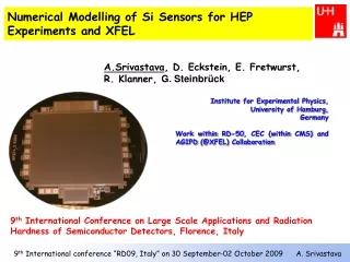
Numerical Modelling of Si Sensors for HEP Experiments and XFEL A.Srivastava, D. Eckstein, E. Fretwurst, R. Klanner, G. Steinbrück Institute for Experimental Physics, University of Hamburg, Germany Work within RD-50, CEC (within CMS) and AGIPD (@XFEL) Collaboration 9th International Conference on Large Scale Applications and Radiation Hardness of Semiconductor Detectors, Florence, Italy
Outline • Motivation to develop radiation harder detectors • Introduction – • Macroscopic radiation damage in Si detectors • Sensor simulation • :Sensor model/experiment • :Physical models and Synopsis-TCAD simulation procedure • :Simulation work done • Inclusion of radiation effects (surface, bulk) • Conclusion and next steps 2
5 years 10 years 2500 fb-1 500 fb-1 Main Motivations for R & D on Radiation Tolerant Detectors • LHC, L=1034cm-2s-1(14 TeV pp collider, 25 ns bunch spacing • Φneq. (r=4cm) ~3·1015cm-2 • Super-LHC, L=1035cm-2s-1Φneq. (r=4cm) ~1.6·1016cm-2 • Detector for European Free-Electron-Laser XFEL at DESY, Hamburg (start in 2013) :Photon fluxes up to: 1016(12 keV /cm2 ≙ 109 Gy [109 J/kg] • (200 ns distance between the pulses) 5 (Simulation by M. Huntinen for CMS) 3
Introduction Macroscopic Radiation Damage Effects in Silicon Detectors • Bulk (crystal) damage due to Non Ionizing Energy Loss (NIEL) • (displacement damage, point defects and cluster defects) • I. Change of effective doping concentration Neff (full depletion voltage VFD) • II. Increase of leakage current (increase of shot noise, thermal runaway) • III. Increase of charge carrier trapping (reduced charge collection efficiency (CCE)) • Surface damage due to Ionizing Energy Loss (IEL) I. Charge build-up in SiO2(shift of flatband voltage Vfb, breakdown at critical corners, change of interpixel capacitance/resistance) II. Traps at Si-SiO2 interface III. Surface generation current (increase shot noise) 4
Sensor Simulation including Radiation Effects • . Simulation of non-irradiated sensors • . Inclusion of radiation effects based on experimental results • Program used: TCAD from Synopsis Physical model used: • SRH (Shockley-Read-Hall) recombination statistics • Recombination through deep level traps • Impact ionization ( determine breakdown voltage) • Trap model • Doping dependent mobility and high field saturation model • Trap to trap interaction model for charge exchange • Fixed oxide charges+ traps at Si/SiO2 interface Compare results to analytical calculations for cross-check 5
Sensor Simulation: for Particle Physics • Simple p+ on n PAD diode (0.25 cm2) to verify simulations SimulatedPAD Si Sensor model Method:Obtain parameters from experimental data and put into simulation to check data are reproduced 6
Four Trap Level Model for n-type MCz Si Sensors • *Modified cross-sections for n-type MCz Si sensor @RT=300K βn=3.66x10⁻¹⁶ cm2/ns and βp=4.92x10⁻¹⁶ cm2/ns • **σp for E5,H152K to agree with data • ***Cluster effect taken into account by increasing the introduction rate of the cluster related defect center E5 by an one order of magnitude 7
Comparison with Experiments No charge exchange taken in E5(-/0) H152K(0/-) • Good agreement between simulation, experimental data and model (ii) for VFD and Leakage current • Theoretical calculations underestimate simulated and experimental current values 8
Effect of Generation Life Time on E-field for 1x10¹⁴ neq./cm2 E-Field expected from double junction g=4.5x10⁻⁷ sec g=4.5x10⁻⁹ sec Electric field (V/cm) versus device depth (μm) In base region-field –> 100 – 1000 V/cm depends on g • Double junction for fluence of 1x10¹⁴ neq./cm2 dueto occupation of traps • Generation life time (deep traps) affects the E-field 9
Sensor Simulation: In the Framework of CEC (CMS) Layout for Near-Far Strixel Baby Si strixel Sensor • First step in simulation: Compare 2-D AC-coupled strixel sensor with 3-D AC-coupled strixel sensor 10
2-D and 3-D Strixel Sensor Simulation • Different Strixel design proposed under CEC like Si strixel (1 metal), double metal layer, near far strixel, pitch adapter integrated into Si strixel sensor 11
Comparison of I/V Characterstics for 2-D and 3-D 2-Strixel Si Sensor 13
Comparison of C/V Characterstics for 2-D and 3-D Strixel Si Sensor Applied bias=100 V, frequency=1 MHz 3-D C/V 2-D C/V CAC CAC CIiM2, CIjM1, Nox=1e12 CIiIj (Cint), Nox=1e12 CIiM2, CIjM1, Nox=1e12 CIiIj (Cint), Nox=1e12 CIiIj , Nox=0.7e11 CIiIj (Cint), Nox=0.7e11 CIiM2, CIjM1, Nox=0.7e11 CIiM2, CIjM1, Nox=0.7e11 CIiM2, CIjM1, Nox=0 CIiIj (Cint), Nox=0 • Diff. of C/V curve due to different geometry of the 2-D and 3-D p+ electrodes • CAC in good agreement with theoretical calculation for both 2-D/3-D • Detector capacitances increases @VFD with surface charges • Up to 0.7x1011 cm-2 Nox, capacitance b/w the p+-strips (Cint) higher than Al-strips. But, for Nox=1x1012 cm-2, vice versa 14
Sensor Simulation: for X-FEL X-ray Sensor (AGIPD) CTR- current terminating ring, CR- Current ring, GR- Guard ring 15
Surface Damage due to 10 keV X-Rays Results from gated diode measurements for 5 MGy Nox=2 x1012 cm-2, Acceptor@Ec-E=0.35eV,σ=0.05 eV,Nit=4x1012 cm-2 Acceptor@Ec-E=0.6 eV,σ=0.05 eV,Nit=4x1013 cm-2 16
Simulation of Guard ring Structure for 5 MGy • VBD observed @995 V, Emax observed on curvature of junction • Compensation of electric field in presence of interface trap and thus low field and high VBD(VBD=299V for Nox=2x1012 cm-2) 17
Conclusion and Next Steps • Detailed sensors simulation for radiation damage effects • -Bulk damage induced by hadrons • Good description of leakage current + depletion voltage including “double junction” • Simulation of CEC strixel sensors started • (comparison of 2-D with 3-D simulation) • -Surface damage induced by X-Rays • Detailed simulation of measurements with gated diodes (not shown) • extraction of relevant parameters • Simulation of radiation damage for guard ring started • Next Steps • Mixed irradiation model for n-type MCz Si – In process of upgrade • for CCE study of an irradiated sensors (for Avalanche Multiplication effect • Comparison of n+ in n and p+ in n pixel for I/V and C/V: AGIPD 18
Back-up slides Next Step 19
Advanced SFH modelsfor Avalanche Multiplication • The recipe: • Relax the assumption on the trap introduction rate (changes with fluence and particles) • Let the parameters (NA, ND – vary with fluences, sA/De, sA/Dh – fitting and calculated@300K • Keep the traps energy levels (EA, ED) to the exp. values • Normalized to Exp. Room tem. @ 293K • Constraints to the model: • Charge collection profiles (at different Vbias and Φeq) • Trapping rates • Generated leakage current βe/h @T calculated/experimental from G.K. thesis Feq known 20
Detector simulation Charge transport ROOT Analysis Trapping Synopsis ISE TCAD n-MCz four level deep traps models (DESSIS) 3-D Electric field mesh Trapping times from literature ROC+FED response Electronic response + data formatting Charge deposit PIXELAV 21
Numerical modelling of radiation damage of Si sensor based on emission-capture dynamics of deep trap The leakage current at full depletion (VFD) and effective doping concentration can be calculated by following expressions; i.e. I(300K) =1.76 x I(293K) (i) (ii) 22
Theoretical Calculation • For 2-D simulaton, half of strixel width (W/2)=12.5µm, Length of strixel(L)= 1 µm (default length) and for 3-D simulation, L=75 µm Coupling capacitance, • Ignoring surface effects, the leakage current @VFD(generation current of the • depletion region: IGEN) can be calculated for 2 strixel Si sensor and 23