Download
1 / 45
480 likes | 830 Views
Trenchless Pipeline Construction in reference to QCS 2010. Prepared by: Dennis M. B. WSO Chairman of Education & Training Committee Lead HSE Engr. For Tender and Technical Preparation - Doha, Qatar PHSSE Manager of CAT for Oil and Gas Project – Abu Dhabi

E N D
Trenchless Pipeline Constructionin reference to QCS 2010 Prepared by: Dennis M. B. WSO Chairman of Education & Training Committee Lead HSE Engr. For Tender and Technical Preparation - Doha, Qatar PHSSE Manager of CAT for Oil and Gas Project – Abu Dhabi HSE Manager of Dorsch Consult – Abu Dhabi Sr. HSE Engr. of TAK Design and Consultant - Dubai
Scope This presentation includes construction of pipeline by microtunneling, pipejacking or other trenchless methods. A thorough understanding on the HSE requirements on the above scope, including: • Appraisal of HSE Technical Documentations • Risk Assessment • EIA
References: QCS 2010 being referred to the following: • BS 2494:1986 - Specification for elastomeric joint rings for pipe work and pipelines • BS 5228-2:2009 - Code of practice for noise and vibration control on construction and open sites Vibration • BS 6164:2001 - Code of practice for safety in tunneling in the construction industry (we now have 2011 edition of this standard) Workshop Focus: • BS OHSAS 18001:2007 • ISO 14001:2004
Definition of terminologies Pipejacking – Technique for constructing pipeline by thrusting pipes or other permanent lining of performed units progressively into the ground by means of jacks or similar equipment while excavation proceeds to the leading end. Microtunneling – Small diameter tunneling technique employing mechanical excavation methods usually within a non-man entry guided tunnel boring machine with primary lining inserted behind by jacking Shaft – Excavated thrust and reception pits used for tunneling operations.
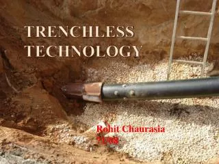
Definition of terminologies Trenchless technology is a type of subsurface construction work that requires few trenches or no continuous trenches. It is a rapidly growing sector of the construction and civil engineering industry. It can be defined as "a family of methods, materials, and equipment capable of being used for the installation of new or replacement or rehabilitation of existing underground infrastructure with minimal disruption to surface traffic, business, and other activities."
Consideration in Planning stage: 1. Urban Underground condition.2. Existing Utilities.3. Banks and Palaces4. Ground/Soil Classification5. Mechanical Condition6. Underground water, Water Level7. Water Resettlements
Submittals 1. The contractor shall submit complete data and details for the trenchless pipeline construction for the engineer’s approval as follows: • Structural design calculations for the trenchless pipeline and temporary works. • Shop Drawing • Material Specifications • Method Statement which shall include • Name and experienced of specialist subcontractor • Detailed procedure for the works • List of all construction plant and tools • Preconstruction activities (geotechnical investigation including test pits) • Safety Procedures • Handling and fixing of the inner pipe in the case of pipejacking with larger diameter pipes • Program of work
Submittals e) Design of thrust and reception shafts and detailed drawings f) Dewatering arrangements and disposal of groundwater g) Methods of dealing different ground conditions h) Equipment layout at the thrust and reception shafts i) Details of sleeving system j) Ventilation K) Lighting and communications l) Disposal of surplus excavated material m) Pilot bore 2. Contractor shall not procure materials or begin construction of the work until the engineer has approved all submittals. The engineer’s approval shall not relieve the Contractor of his obligations under Contract.
Specialist Subcontractor The Contractor shall employ an approved specialist subcontractor experienced in trenchless methods for the pipeline construction.
Trenchless construction includes such construction methods as: • tunneling, • microtunneling (MTM), • horizontal directional drilling (HDD) also known as directional boring, • pipe ramming (PR)/pipe jacking (PJ), • moling, • horizontal auger boring (HAB) and other methods for the installation of pipelines and cables below the ground with minimal excavation. • Large diameter tunnels such as those constructed by a tunnel boring machine (TBM), and drilling and blasting techniques are larger versions of subsurface construction. The difference between trenchless and other subsurface construction techniques depends upon the size of the passage under construction. • The method requires considering soil characteristics and the loads applied to the surface. In cases where the soil is sandy, the water table is at shallow depth, or heavy loads like that of urban traffic are expected, the depth of excavation has to be such that the pressure of the load on the surface does not affect the bore, otherwise there is danger of surface caving in.
Trenchless construction methods • Microtunneling - Microtunnel boring machines are very similar to tunnel boring machines (TBM) but on a smaller scale. These machines generally vary from 0.61 to 1.5 meters (2 ft 0.02 in to 4 ft 11 in) but smaller and larger machines have existed. Usually the operator controls the machine from a control room on the surface of the ground. The operator is given constant feedback about the machine’s location, orientation and hydraulic devices via a computer console. Most machines also have video cameras set up to give the operator more information. The operator can then control the MTBM and the jacking frame from the safety of the control room.
Microtunneling cont’d • In most microtunneling operations the pipe is inserted from the entry and pushed behind the machine. This is a process often called pipe jacking. As the machine advances, more tunnel liner is pushed from the entrance. Thus, the speed of the advancing machine is controlled by the speed at which the pipe is inserted into the entrance. • As the length of tunnel increases, the friction of the ground around the pipe increases as well. Usually, two practices are used to minimize this friction. First, over-cutting is used to give a slight gap between the inner edge of the tunnel and the outer edge of the liner. Usually this is achieved by using a cutter wheel with a diameter ½ inch (12mm) to 4 inches (100mm) larger than the outside diameter of the liner. Secondly, an economical and ecologically friendly lubricant, often bentoniteslurry, is injected into this gap. In addition to lubrication, the pressure of the lubricant prevents the gap from collapsing. • While friction can be reduced, it can never be eliminated, and so hundreds of tons of force are required to push the machine and liner into the ground. A large “jacking frame” is required to produce these forces. In most cases the entrance must be modified to support this frame and the forces it generates. • In addition to the jacking frame, smaller jacks, called “interjacks”, may be inserted between sections of tunnel liner. These push the two sections of liner apart. Friction on the liner sections between the interjack and the tunnel entrance helps to prevent the liner from sliding out backwards. So while the liner behind the interjack does not move, those sections in front of it receive additional pushing force.
Trenchless construction methods 2. Pipe bursting -
Trenchless construction methods 3. Directional drilling (or slant drilling) is the practice for drilling non-vertical wells. It can be broken down into three main groups: oilfield directional drilling, utility installation directional drilling (horizontal directional drilling), directional boring, and surface in seam (SIS), which horizontally intersects a vertical well target to extract coal bed methane.
Wells are drilled directionally for several purposes: • Increasing the exposed section length through the reservoir by drilling through the reservoir at an angle • Drilling into the reservoir where vertical access is difficult or not possible. For instance an oilfield under a town, under a lake, or underneath a difficult-to-drill formation • Allowing more wellheads to be grouped together on one surface location can allow fewer rig moves, less surface area disturbance, and make it easier and cheaper to complete and produce the wells. For instance, on an oil platform or jacket offshore, 40 or more wells can be grouped together. The wells will fan out from the platform into the reservoir(s) below. This concept is being applied to land wells, allowing multiple subsurface locations to be reached from one pad, reducing costs. • Drilling along the underside of a reservoir-constraining fault allows multiple productive sands to be completed at the highest stratigraphic points. • Drilling a "relief well" to relieve the pressure of a well producing without restraint (a "blowout"). In this scenario, another well could be drilled starting at a safe distance away from the blowout, but intersecting the troubled wellbore. Then, heavy fluid (kill fluid) is pumped into the relief wellbore to suppress the high pressure in the original wellbore causing the blowout.
New technologies • Horizontal Directional Drilled Wells (HDDW) is a new technology developed to offer new solutions for a variety of applications regarding the use of water. Examples using this technology are groundwater extraction or infiltration, dike stabilization, desalination, heat and cold storage, etc.The technology forms the basis of a filtration system which is tuned to the local soil composition. Hereby a filter tube with the right diameter and the right dimensions of the filter holes is placed in the borehole. In cases where the soil composition is too diverse the filter tube is surrounded by an artificial area filter to create the optimal soil structure ensuring maximum functionality.
Directional Boring/HDD(Horizontal Directional Drilling) Directional boring, commonly called horizontal directional drilling or HDD, is a steerable trenchless method of installing underground pipes, conduits and cables in a shallow arc along a prescribed bore path by using a surface-launched drilling rig, with minimal impact on the surrounding area. Directional boring is used when trenching or excavating is not practical. It is suitable for a variety of soil conditions and jobs including road, landscape and river crossings. Installation lengths up to 2000 m have been completed, and diameters up to 1200 mm have been installed in shorter runs. Pipes can be made of materials such as PVC, polyethylene, polypropylene, Ductile iron, and steel if the pipes can be pulled through the drilled hole. Directional boring is not practical if there are voids in the rock or incomplete layers of rock. The best material is solid rock or sedimentary material. Soils with cobble stone are not recommended. There are different types of heads used in the pilot-hole process, and they depend on the geological material.
Directional Boring/HDD(Horizontal Directional Drilling) Equipment • The equipment used in a horizontal directional drilling depends on the outer diameter of the pipe, length of the run, ground conditions and the surroundings above ground. For the large bores, directional drills equipped with as much as 1 320 000 lb (or more) of thrust/pullback (Vermeer D1320x900)is used in conjunction with a mud reclaimer, excavator, and multiple pumps and hoses to supply the drilling fluid to the drillstem. Directional drilling stem is made from heat-treated high-carbon steel for strength and ships in diameters of8 - 15 cm. Drill stem sections are manufactured in 3.0 or 4.6 and also 9.1 meter lengths and have male threading on one end, and female on the other. It is common for a directional drill to carry as much as 305 m of rod on board. Drilling heads come in multiple designs and depends on the rock or soil being penetrated. The drilling head has multiple water ports to allow removal of material. A talon bit involves the carbide-tipped cutters. These allow for steering and cutting the material. Another head is a mud-motor that is used in rocky landscapes. • Furthermore, supporting equipment is needed to assist directional-drilling or HDD to work smoothly, such as drilling mud recycling system, shale shaker, mud cleaner, centrifugal pump, mud tanks, etc.
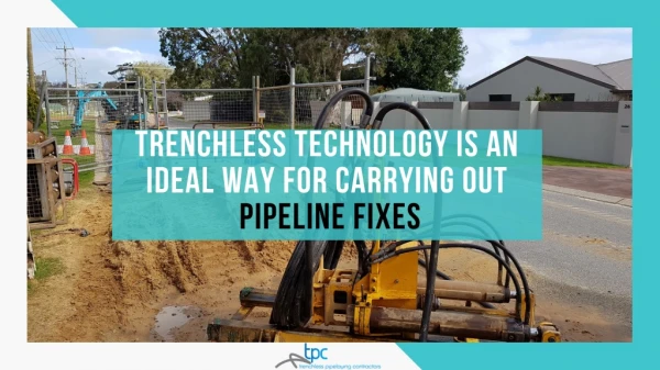
Directional Boring/HDD(Horizontal Directional Drilling) Technique • Directional boring is used for installing infrastructure such as telecommunications and power cable conduits, water lines, sewer lines, gas lines, oil lines, product pipelines, and environmental remediation casings. It is used for crossing waterways, roadways, shore approaches, congested areas, environmentally sensitive areas, and areas where other methods are costlier or not possible. It is used instead of other techniques to provide less traffic disruption, lower cost, deeper and/or longer installation, no access pit, shorter completion times, directional capabilities, and environmental safety. • The technique has extensive use in urban areas for developing subsurface utilities as it helps in avoiding extensive open cut trenches. The use requires that the operator have complete information about existing utilities so that he can plan the alignment to avoid damaging those utilities. Since uncontrolled drilling can lead to damage, different agencies/government authorities owning the urban right-of-way or the utilities have rules for safe work execution. For standardization of the techniques, different trenchlesstechnology promoting organizations have developed guidelines for this technique.
Directional Boring/HDD(Horizontal Directional Drilling) Process • Starting pit with pilot hole and some drilling fluid in the pit • The process starts with receiving hole and entrance pits. These pits will allow the drilling fluid to be collected and reclaimed to reduce costs and prevent waste. The first stage drills a pilot hole on the designed path, and the second stage (reaming) enlarges the hole by passing a larger cutting tool known as the back reamer. The reamer's diameter depends on the size of the pipe to be pulled back through the bore hole. The driller increases the diameter according to the outer diameter or the conduit and to achieve optimal production. The third stage places the product or casing pipe in the enlarged hole by way of the drill stem; it is pulled behind the reamer to allow centering of the pipe in the newly reamed path. • Horizontal directional drilling is done with the help of a viscous fluid known as drilling fluid. It is a mixture of water and, usually, bentonite or polymer continuously pumped to the cutting head or drill bit to facilitate the removal of cuttings, stabilize the bore hole, cool the cutting head, and lubricate the passage of the product pipe. The drilling fluid is sent into a machine called a reclaimer which removes the drill cuttings and maintains the proper viscosity of the fluid. Drilling fluids hold the cuttings in suspension to prevent them from clogging the bore. A clogged bore creates back pressure on the cutting head, slowing production.
Pipe ramming/Pipe Jacking • Pipe ramming (or pipe jacking in British English) is a trenchless method for installation of steel pipes and casings. Distances up to 30m (150 ft) long and up to 1,500mm (60-inches) in diameter are feasible, although the method can be used for much longer and larger installations. [The method is the most useful for shallow installations under railway lines and roads, where other trenchless methods could cause surface settling or heaving. The majority of installations are horizontal, although the method can be used for vertical installations. • The method uses pneumatic percussive blows to drive the pipe through the ground. The leading edge of the pipe is almost always open, and is typically closed only when smaller pipes are being installed. Its shape allows a small overcut (to reduce friction between the pipe and soil and improve load conditions on the pipe) and to direct the soil into the pipe interior instead of compacting it outside the pipe. These objectives are usually achieved by attaching a soil-cutting shoe or special bands to the pipe. • Further reduction of friction is typically achieved with lubrication, and different types of bentonite and/or polymers can be used (as in horizontal directional boring) for this purpose. Spoil removal from the pipe can be done after the entire pipe is in place (shorter installations). If the pipe containing the spoil becomes too heavy before the installation is complete, the ramming can be interrupted and the pipe cleaned (longer installations). Spoil can be removed by auger, compressed air or water jetting.
Drilling and Blasting • Before the advent of tunnel boring machines, drilling and blasting was the only economical way of excavating long tunnels through hard rock, where digging is not possible. Even today, the method is still used in the construction of tunnels, such as in the construction of the Lötschberg Base Tunnel. The decision whether to construct a tunnel using a TBM or using a drill and blast method includes a number of factors such as: • Tunnel length • Managing the risks of variations in ground quality • Required speed of construction • The required shape of the tunnel • Tunnel length is a key issue that needs to be addressed because large TBMs for a rock tunnel have a high capital cost, but because they are usually quicker than a drill and blast tunnel the price per meter of tunnel is lower.[1] This means that shorter tunnels tend to be less economical to construct with a TBM and are therefore usually constructed by drill and blast. Managing ground conditions can also have a significant effect on the choice with different methods suited to different hazards in the ground.
Moling • Moling is a trenchless method used to lay pipes. During the moling process, a pneumatically-driven machine known as a mole forces its way through the soil along the desired path of the pipe. Moling avoids the need to dig a trench and can be used to lay water pipes and the heating coils of heat pump systems. • Recently moles that are steerable have been developed allowing an operator to correct the track of the mole and to achieve curved bores. • The standard approach to moling is to dig a hole about 1 m square and 2 m deep. Such a hole is small enough that it can be dug by hand instead of by machine in inaccessible locations. The mole is then entered into the earth on the horizontal face at the bottom of this hole. A destination hole of similar proportions is also dug, and this is where the mole emerges. The mole itself is a steel cylinder about 60 cm long and 6 cm in diameter. It works as a pneumatic cylinder with pulsed compressed air causing the head of the mole to repeatedly hammer against the soil in front of the mole. Once the mole has passed through the earth the pipe can be pulled through the long horizontal hole.
TBM(Tunnel Boring Machine) A tunnel boring machine (TBM) also known as a "mole", is a machine used to excavate tunnel with a circular cross section through a variety of soil and rock strata. They can bore through anything from hard rock to sand. Tunnel diameters can range from a meter (done with micro-TBMs) to 19.25 m to date. Tunnels of less than a meter or so in diameter are typically done using trenchless construction methods or horizontal directional drilling rather than TBMs.
TBM(Tunnel Boring Machine) Tunnel boring machines are used as an alternative to drilling and blasting (D&B) methods in rock and conventional "hand mining" in soil. TBMs have the advantages of limiting the disturbance to the surrounding ground and producing a smooth tunnel wall. This significantly reduces the cost of lining the tunnel, and makes them suitable to use in heavily urbanized areas. The major disadvantage is the upfront cost. TBMs are expensive to construct, and can be difficult to transport. However, as modern tunnels become longer, the cost of tunnel boring machines versus drill and blast is actually less—this is because tunneling with TBMs is much more efficient and results in a shorter project.
TBM(Tunnel Boring Machine) • Tunnel boring machines are used as an alternative to drilling and blasting (D&B) methods in rock and conventional "hand mining" in soil. TBMs have the advantages of limiting the disturbance to the surrounding ground and producing a smooth tunnel wall. This significantly reduces the cost of lining the tunnel, and makes them suitable to use in heavily urbanized areas. The major disadvantage is the upfront cost. TBMs are expensive to construct, and can be difficult to transport. However, as modern tunnels become longer, the cost of tunnel boring machines versus drill and blast is actually less—this is because tunneling with TBMs is much more efficient and results in a shorter project. • The largest diameter TBM, at 19.25 m, built by Herrenknecht AG for a recent project in Orlovski Tunnel, St.Petersburg. The machine was built to bore through soft ground including sand and clay. The largest diameter hard rock TBM, at 14.4 m, was manufactured by The Robbins Company for Canada's Niagara Tunnel Project. The machine was used to bore a hydroelectric tunnel beneath Niagara Falls. The machine has been named "Big Becky" in reference to the Sir Adam Beckhydroelectric dams to which it is tunnelling to provide an additional hydroelectric tunnel.
Trenchless rehabilitation includes such construction methods as • sliplining, • thermoformed pipe, • pipe bursting, • shotcrete, • gunite, • cured-in-place pipe (CIPP), • grout-in-place pipe, • mechanical spot repair, and other methods for the repair, rehabilitation, or replacement of existing buried pipes and structures without excavation, or at least with minimal excavation. Mechanical spot repair is applied where damaged pipelines require the re-instatement of structural integrity. Sliplining, CIPP, and thermoformed pipe lining involve pulling or inverting a new liner into an existing pipe, then applying heat and/or pressure to force the liner to expand to fill the pipe. CIPP technologies combine a carrier (felt or fibreglass) impregnated with heat, ultraviolet light, or ambient curable resin to form a "pipe within a pipe". Pipe bursting fractures a pipe from the inside and forces the fragments outwards while a new pipe is drawn in to replace the old.[2] The other methods are primarily for fixing spot leaks. Trenchless rehabilitation methods are generally more cost-effective than traditional exhume (dig) and replace methods.
Russian operating company NCC (Nevskaya Concession Company) has placed an order with Herrenknecht for the construction of a world record breaking 19.25m diameter Mixshield TBM. The machine will bore the 1km long Orlovski Tunnel linking the centre of St Petersburg via an underpass of the Neve River, and will be the largest TBM ever built.
Herrenknecht'sworld record TBMs • 1995 Adler Tunnel, Switzerland Single Shield TBM12.535m • 1997Elbe Tunnel, GermanyMixshield14.200m • 2001Lefortovo Tunnel, RussiaMixshield14.200m • 2004 Silver Forest Tunnel, RussiaMixshield14.200m • 2005M30, Spain EPB Shield15.200m • 2006Shanghai Yangtze River Tunnel, China2 Mixshields15.430m • 2010 Sparvo, Italy EPB Shield15.550m • 2011 Orlovski Tunnel, RussiaMixshield19.250m
Tunnel Boring Machine that was used at Yucca MountainConstructed as Nuclear Waste Depository
The Yucca Mountain Nuclear Waste Repository as designated by the NWPA Amendments of 1987, was to be a deep geological repository storage facility for spent nuclear reactor fuel and other high level radioactive waste. Federal funding ended in 2010. It was to be located on federal land adjacent to the Nevada Test Site in Nye County, Nevada, about 80 mi (130 km) northwest of the Las Vegas Valley. The proposed repository was within Yucca Mountain, a ridge line in the south-central part of Nevada near its border with California. • Although the location has been highly contested by both environmentalists and non-local residents in Las Vegas, which is over 100 miles (160 km) away, it was approved in 2002 by the United States Congress. However, under the Obama Administration funding for development of Yucca Mountain waste site was terminated effective via amendment to the Department of Defense and Full-Year Continuing Appropriations Act, passed by Congress on April 14, 2011. The US GAO stated that the closure was for political, not technical or safety reasons. This leaves United States civilians without any long term storage site for high level radioactive waste, currently stored on-site at various nuclear facilities around the country, although the United States government can dispose of its waste at WIPP, in rooms 2,150 feet (660 m) underground. The Department of Energy is reviewing other options for a high-level waste repository. The Blue Ribbon Commission established by the Secretary of Energy released its final report on January 26, 2012. It expressed urgency to find a consolidated, geological repository, but also that any future facility should have input from the citizens around it.