Download

1 / 23
230 likes | 351 Views
This experience report outlines the implementation and results of the Alignment Diagnostic System (ADS) for the Linac Coherent Light Source (LCLS) project at SLAC. Over a period of two days, the system monitored the stability of the undulator segments and tracked the position of girders using hydrostatic leveling sensors and wire position monitors, achieving a resolution of less than 1 micrometer. The report discusses various challenges faced, solutions implemented, and the overall performance of the alignment system, ultimately confirming its effectiveness in maintaining precise alignment critical for accelerator functionality.

E N D
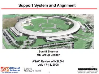
Experience Report with the Alignment Diagnostic System Georg Gassner September 17th 2010
Injector (35º) at 2-km point Existing 1/3 Linac (1 km) (with modifications) New e- Transfer Line (340 m) X-ray Transport Line (200 m) Undulator (130 m) Near Experiment Hall UCLA Far Experiment Hall Linac Coherent Light Source at SLAC X-FEL based on last 1-km of existing 3-km linac 1.5-15 Å (14-4.3 GeV)
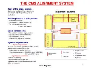
Undulator System 3.4m undulator magnet Quadrupole Wire Position Monitor X-translation (in/out) Hydrostatic Leveling Sensor CAM based 5 DOF Motion control Sand-filled Thermally Isolated Supports Experience report with the Alignment Diagnostic System Page 3
Goal of the Alignment Diagnostic System • Question: Do we know how stable the LCLS tunnel and the Undulator will be? Answer: No, we don’t! Advice: Install a girder position monitoring system….. 1 2 i 33 Undulator: 33 Girder, 132 m Y-pos X-pos ... and track each girder relative to the Least Square Fit of all girders! Resolution: < One Micrometer Measurement duration: > Weeks, no drifts Building Blocks: Hydrostatic Leveling System (HLS) for Y - direction.Experience: Used @ SLAC Wire Position Monitors (WPM) for the X & Y direction.* Experience: FFTB @ SLAC * Original design from DESY as contribution to the FFTB experiment at SLAC, 1991 Experience report with the Alignment Diagnostic System Page 4
Alignment Diagnostics System 1400 mm WPM and HLS operates as one system, called AlignmentDiagnosticSystem, ADS WPM measures: X and Y- positions relative to two stretched wires HLS measures: Y - Positions relative to the water surface level Common Task: • X & Y Positon monitoring of undulator segments • Resolution: < micrometer • Data rate: every minute • Operation: continous Experience report with the Alignment Diagnostic System Page 5
Results: Two days of tracking– no cam or stage movement Hydrostatic leveling sensor readings - vertical 2010/3/10 0:00 2010/3/9 0:00 2010/3/8 0:00 10 µm Experience report with the Alignment Diagnostic System Page 6
Results: Two days of tracking– no cam or stage movement Wire position sensor readings - vertical 2010/3/10 0:00 2010/3/9 0:00 2010/3/8 0:00 10 µm Experience report with the Alignment Diagnostic System Page 7
Results: Two days of tracking– no cam or stage movement ADS response - vertical 2010/3/10 0:00 2010/3/9 0:00 2010/3/8 0:00 Undulator hall below ground Stretched wire 10 µm Experience report with the Alignment Diagnostic System Page 8
Results: Two days of tracking– no cam or stage movement Wire position sensor readings - horizontal 2010/3/10 0:00 2010/3/9 0:00 2010/3/8 0:00 10 µm Experience report with the Alignment Diagnostic System Page 9
Results: Two days of tracking– no cam or stage movement ADS response - horizontal 2010/3/10 0:00 2010/3/9 0:00 2010/3/8 0:00 10 µm Experience report with the Alignment Diagnostic System Page 10
Results: normal operation – moving girders ADS response - vertical 2010/9/9 17:37 2010/9/8 17:37 10 µm Experience report with the Alignment Diagnostic System Page 11
Problem (1): HLS time delay Water takes several hours to settle if movement is big enough to require water to redistribute Our pipes are mounted to the girder, if a girder moves all the water in the 4m pipe section has to redistribute Experience report with the Alignment Diagnostic System Page 12
Problem (2): Best fit solution Reference line Girder positions Positions are given in respect to reference line which is the best fit solution. If one girder is moved deliberately this would change the reference line and indicate that all girders have moved. Experience report with the Alignment Diagnostic System Page 13
Problem (2): Best fit solution Reference line Girder positions Positions are given in respect to reference line which is the best fit solution. If one girder is moved deliberately this would change the reference line and indicate that all girders have moved. Experience report with the Alignment Diagnostic System Page 14
Problem (2): Best fit solution Reference line Girder positions Positions are given in respect to reference line which is the best fit solution. If one girder is moved deliberately this would change the reference line and indicate that all girders have moved. Girder motions are communicated to the ADS system and taken into account in the adjustment Experience report with the Alignment Diagnostic System Page 15
Results: normal operation – moving girdersQuick response mode ADS response - vertical 2010/9/9 17:37 2010/9/8 17:37 10 µm Experience report with the Alignment Diagnostic System Page 16
Results: normal operation – moving girdersQuick response mode ADS response - vertical 2010/9/9 17:37 2010/9/8 17:37 200 µm Experience report with the Alignment Diagnostic System Page 17
Summary Experience report with the Alignment Diagnostic System Page 18 • ADS achieved original goal of monitoring quadrupole position to the micrometer level • Add-ons: • Cam/stage system motion is taken into account for reference line fit. • Since girders are moved by tens of µm, a “quick response” algorithm to monitor the girder position short term had to be added.
Introduction • Text goes here. • Since 2009 an Alignment Diagnostic System (ADS) has been operating at the undulator of the new Linac Coherent Light Source at SLAC National Laboratory. The undulator spans a distance of 132 meters and is structured into 33 segments. Each segment is equipped with four hydrostatic leveling sensors and three wire position monitors. This report describes the set up and reflects long time experience gained with ADS. Experience report with the Alignment Diagnostic System Page 20
Monitor Length 74 Millimeter Monitor GAP 8 Millimeter Square Wire Position Monitor * * Original design from DESY as contribution to the FFTB experiment at SLAC, 1991 Experience report with the Alignment Diagnostic System Page 21
LCLS - WPM system sensitivity – e.g. response on social noise - Frequency analysis of the 140 m stretched wire. - 40 seconds of data acquisition - Monitor at the middle of the 140 m wire X 3.925 Hz: 0.027 µm 2nd and higher even harmonics missing Y Monitor outside the middle of the 140 m wire X 2nd and higher even harmonics visible 3.95 Hz: 0.0086 µm 18.375Hz: 0.0046 µm Y 1st 1.3Hz 2nd 2.6Hz 3rd 3.9Hz 4th 5.2Hz 5th 6.5Hz 6th 7.8Hz 7th 9.1Hz 8th 10.4Hz 9th 11.8Hz 10th 13.1Hz 11th 14.4Hz 12th 15.7Hz 13th 17.0Hz 14th 18.3Hz 15th 19.6Hz Experience report with the Alignment Diagnostic System Page 22
WPM Capacitive WPM Capacitive Capacitive Ultra sonic Drawing: Courtesy by Scott Doran, ANL Integration of ADS to girder: Artist view Experience report with the Alignment Diagnostic System Page 23