Download
1 / 120
1.29k likes | 1.82k Views
VSX-49TX. 2005 Pioneer Home Audio Seminar. Pioneer Electronic Service, Inc. 2005. Welcome one and all! Your instructor…Dave Kraus. Introduction. Why the VSX49TX? The VSX49TX is not current product, however it tends to be the most difficult to repair! What will be covered?

E N D
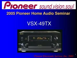
VSX-49TX 2005 Pioneer Home Audio Seminar Pioneer Electronic Service, Inc. 2005
Welcome one and all! Your instructor…Dave Kraus
Introduction Why the VSX49TX? The VSX49TX is not current product, however it tends to be the most difficult to repair! What will be covered? The receiver in general; more specifically… DSP circuitry Display & System Micro Amplifier and Protection circuit. Power Supply Trouble Shooting Tips
This seminar will be specifically about troubleshooting techniques, no operation instructions, no theory!
What will you get out of this? You will learn the most successful troubleshooting methods designed to get the unit on and off your bench as quickly as possible. You will learn more accurate repair techniques and avoid having to replace costly boards on out-of-warranty units. Replacing expensive boards can sometimes mean the difference between getting the repair or having the customer walk!
Bright Idea In an effort to keep you awake, we will break for minimum of 10 minutes every other hour of training!
Topics we will cover Minor disassembly DSP circuitry Amplifier & Protection circuits System Microprocessor Display Microprocessor Power Supply Additional resources
Disassembly • Remove no more than you have to! • Use caution when removing the back panel screws. They are different ! You are using your ESD wrist strap aren’t you? Sorry folks. ESD precautions are a fact of life! Why do your work over and over again due to static damaged components!
To start… 1. Place unit as pictured and remove top, bottom and side covers. 2. Prop up unit as pictured for easy access. 3. Remove all screws holding the DSP boards, as well as any attached connectors or wire ties.
Remove only the screws necessary as shown below. Why spend more time than you have to?
Use caution when removing screws. There are 3 different types !
Keep track of the screw types. Correct place for screw with integral flat and attached star washer.
With the screws removed, gently pull back on the back panel, while extracting the DSP and DSP3 assemblies.
Digital Signal Processing The DSP circuit consists of 3 boards 1. AWK7719 DSP ASSY 2. AWK7727 DSP3 ASSY 3. AWK7725 DAC10 ASSY
DSP assemblies DAC10 ASSY #3 DSP3 ASSY #2 DSP ASSY #1
Setup DVD Digital Input either Coaxial or Optical Speaker setup 5.1 or 5 channel(without Subwoofer) Must use DVD with Surround information {Be sure to look at front panel display} For the purpose of this seminar, we will follow the left surround channel only. Indicators must illuminate for all channels driven. No illumination, no audio!
For your reference onlyDepending on the accuracy of your scope, this voltage, 5 volts (TTL level), may vary by + or - .5 volts.
Test point DIR & DIT Pin 3 IC112 DIR & DIT Pin 3 In
Test point DIR&DIT IC101 Pin 3 More noise than signal IC101 Pin 3 DIR & DIT In
Test point DIR&DIT Pin 25 IC101 Pin 25 DIR&DIT Out
Test point DIR&DIT Pin 25 IC101 Pin 25 DIR&DIT Out
Test point Selector IC112 Pin 3 IC 112 Pin 3 Selector In
Test point IC112 Pin 3 IC112 Pin 3 Selector In
Test point Selector IC112 Pin 4 IC112 Pin 4 Out
Test point Selector IC112 Pin 4 Test Point Pin 4 Out
Test point DSP1 IC301 Pin 6 IC301 DSP1 Pin 6 In
Test point DSP1 IC301 Pin 6 Waveform vary small. More noise than signal!
Test point DSP1 IC301 Pin 12 IC301 DSP1 Pin 12 Out
Test point DSP2 IC401 Pin 11 IC401 DSP2 Pin 11 In
Question… How do I troubleshoot the DSP2 IC? It’s located directly under the DSP3 ASSY. Answer.. Simply remove the DSP3 ASSY. There won’t be any sound output from the unit, but you can scope the digital waveform none the less! DSP2 IC is under here.
DSP2 IC401 Pin 5 Out IC401 DSP2 Pin 5 Out
DSP3 IC501 Pin 6 In IC501 DSP3 Pin 6 In
DSP3 IC501 Pin 12 Out IC501 DSP3 Pin 12 Out
DAC10 CN6002 Pin 11 In DAC10 ASSY CN6002 Pin 11 In