Download
1 / 21
210 likes | 361 Views
Vacuum Phototriodes for the CMS Electromagnetic Calorimeter Endcap. Ken Bell , R.M.Brown, D.J.A.Cockerill, P.S.Flower, P.R.Hobson, B.W.Kennedy, A.L.Lintern, C.W.Selby, O.Sharif, M.Sproston, J.H.Williams CCLRC Rutherford Appleton Laboratory, Didcot, UK Brunel University, Uxbridge, UK

E N D
Vacuum Phototriodes for the CMS Electromagnetic Calorimeter Endcap Ken Bell, R.M.Brown, D.J.A.Cockerill, P.S.Flower,P.R.Hobson,B.W.Kennedy, A.L.Lintern,C.W.Selby, O.Sharif,M.Sproston, J.H.Williams CCLRC Rutherford Appleton Laboratory, Didcot, UKBrunel University, Uxbridge, UK IEEE IMTC Conference – Como – May 2004 Ken Bell - CCLRC Rutherford Appleton Laboratory
Outline • Introduction to CMS Electromagnetic Calorimeter Endcap • Description of CMS Vacuum Phototriodes • Measurements of VPT Performance in a Magnetic Field • Ensuring the Radiation Tolerance • Summary Ken Bell - CCLRC Rutherford Appleton Laboratory
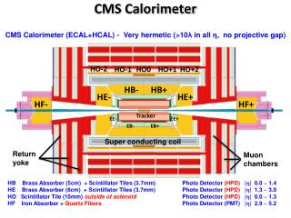
Electromagnetic Calorimeter 7 TeV protons 7 TeV protons B=4T Superconducting coil Total mass : 12,500t Overall Diameter: 15.0m Overall Length: 21.6m Magnetic field: 4T The Compact Muon Solenoid Experiment at the CERN LHC Ken Bell - CCLRC Rutherford Appleton Laboratory
The CMS Electromagnetic Calorimeter • Hermetic calorimeter of scintillating crystals • Quasi-Pointing geometry • PbWO4 crystals (~430nm) 61,200 in barrel 14,648 in endcaps • Length: 6 m • Diameter: 3.5 m • Depth: ~25 X0 • Pb/Si preshower detector in front of endcap crystals • Target energy resolution <1% at E = 100 GeV Endcap geometry based on array of identical 5x5 modules (supercrystals) Ken Bell - CCLRC Rutherford Appleton Laboratory
The Endcap Electromagnetic Calorimeter • Basic endcap unit – Supercrystal • 55 array of tapered crystals, each ~3030220 mm3 • Carbon-fibre alveolar support • PbWO4 crystals • Dense (X0 = 8.9 mm) • Radiation hard • Fast scintillator (90% of light in 100 ns) • Mechanically fragile • Low light yield (~50 photons / MeV) Ken Bell - CCLRC Rutherford Appleton Laboratory
Challenges for the Photodetectors • Operation in magnetic field of 4T • High radiation environment • Dose is strong function of angle wrt incoming proton beams • Barrel: Up to 4 kGy and 1013 n cm-2 in 10 years of LHC running • Endcap: 4–200 kGy and up to 1015 neutrons cm-2 • Fast response required • LHC beam crossing time = 25 ns • Low light yield from PbWO4 • ~50 photons / MeV need photodetectors with internal gain • CMS choices • Barrel – Avalanche PhotoDiodes • Endcap – Vacuum PhotoTriodes (VPTs) • Both custom developed for CMS, in collaboration with industry • VPTs previously developed in HEP for the endcap electromagnetic calorimeters of OPAL and DELPHI at LEP, but radiation levels at LEP much lower and eg OPAL magnetic field 10 lower Ken Bell - CCLRC Rutherford Appleton Laboratory
Light 0V Photocathode 1000V Grid anode 800V Dynode Vacuum Phototriodes for CMS from Research Institute Electron (St Petersburg) Single-gain-stage mesh photomultiplier Bi-alkali No EB effects if VPT axis aligned with magnetic field 10um pitch mesh Anode Mesh transparency ~50% Ken Bell - CCLRC Rutherford Appleton Laboratory
Vacuum Phototriodes for CMS from Research Institute Electron (St Petersburg) • Pre-production order: 500 • Production order: 15,000 VPTs • Delivery spread over 4 years • 7,900 devices presently delivered and tested at B=1.8T • Quantum efficiency typically 22% at 430nm, flat over photocathode area • Mean VPT gain is 10.2 at B=0T Ken Bell - CCLRC Rutherford Appleton Laboratory
Automated VPT Characterisation in a Magnetic Field via 420nm LEDs • Every VPT is measured at 0 B 1.8T and -30o 30o at RAL • A 10% sample of VPTs are measured at B = 4.0T and = 15o at Brunel • Dark currents and noise also measured • Reproducibility of measurements 2% 4.0T Superconducting Solenoid at Brunel 1.8T Dipole Magnet at RAL Ken Bell - CCLRC Rutherford Appleton Laboratory
Arrows indicate angular coverage of CMS end caps VPT Response v/s Angle at B=1.8T • VPT response is maintained over -40o 40o • VPT axis in CMS: 8o < || < 24o wrt to magnetic field (pointing geom) • For VPT axis -30o 30o, EB effects and probability of electron capture on anode grid characteristic periodic behaviour Ken Bell - CCLRC Rutherford Appleton Laboratory
VPT Response v/s Magnetic Field Strength • VPT axis at angle of 15o to the magnetic field • Response ~flat for B>0.8T • Satisfactory performance at B=1.8T is very reliable indicator that VPT will operate well at B=4T Note: the precise details of the reduction in relative response depends on the uniformity of photocathode illumination Ken Bell - CCLRC Rutherford Appleton Laboratory
Relative VPT Response B=4T/B=0T at = 15o • Results on 652 VPTs – note logarithmic Y axis ! • Mean ratio is 0.95 – only 1 VPT has failed our >0.75 requirement Ken Bell - CCLRC Rutherford Appleton Laboratory
VPT Response v/s Angle at B=4T • 1-off hand angle scan of VPT at B=4T • Periodicity now 5o (cf was 10o at B=1.8T) • Ratio consistent with inverse ratio of magnetic field, as expected Ken Bell - CCLRC Rutherford Appleton Laboratory
Ensuring the Radiation Tolerance • Have verified that VPTs are resistant to 1015 n cm-2 fluence expected • VPT faceplates made of rad-hard UV-transmitting borosilicate glass, manufactured in small batches (concern of batch-to-batch variation) • Before each batch is certified for use, several faceplates are irradiated to 20kGy using Co60 source at Brunel. Transmission loss (convoluting with PbWO4 emission spectrum) required to be <10% • Also important that instantaneous dose & neutron fluence don’t upset the performance of the VPTs • Operated VPTs at Co60 source at Brunel and at Cf252 neutron source at University of Minnesota • Saw increase in noise, attributed to photo-electrons liberated by Cerenkov light from relativistic electrons traversing the faceplate • Scaling the rates to the LHC, the effects should be negligible, except very close to the beam pipe Ken Bell - CCLRC Rutherford Appleton Laboratory
Summary • We have developed a new generation of fine-mesh VPTs to meet the demanding requirements of CMS Endcap ECAL • CMS requires 15,000 VPTs. 7,900 devices already delivered • Performance of all delivered VPTs already measured at B=1.8T at RAL • >10% of VPTs also measured at B=4T at Brunel • These measurements correlate well, confirming that VPTs which pass at B=1.8T will operate satisfactorily in CMS at B=4T • VPT radiation tolerance ensured by testing all batches of faceplates • Have verified that instantaneous dose and fluence in CMS will not significantly degrade the VPT performance Ken Bell - CCLRC Rutherford Appleton Laboratory
Back-up Slides… Ken Bell - CCLRC Rutherford Appleton Laboratory
HCAL Barrel ECAL Endcap 0.2 1.2 0.35 0.5 2 ECAL Barrel 5 3 70 20 50 Radiation Environment • 10-year dose in italics (black: at shower maximum inside the crystals) • Neutron fluence in red Ken Bell - CCLRC Rutherford Appleton Laboratory
VPT Photocathode Response • Uniformity of photocathode response • Measured by CMS colleagues in Split, Croatia • Response flat response over photocathode area • Quantum efficiency typically 22% at 430nm With thanks to N.Godinovic, I.Puljak, and I.Soric, University of Split, Croatia, for the use of this data Ken Bell - CCLRC Rutherford Appleton Laboratory
Comparisons of B=0 and B=1.8Tand of B=1.8T and B=4T B=4T at Brunel (Y) v/s B=1.8T at RAL (X) B=1.8T at RAL (Y) v/s B=0 at Research Institute Electron (X) Ken Bell - CCLRC Rutherford Appleton Laboratory
VPT Gain as a function of applied HV • Operating voltage in CMS: VA=1000V, VD=800V • Close to plateau Ken Bell - CCLRC Rutherford Appleton Laboratory
Typical PbWO4 emission spectrum Typical VPT faceplate absorbance spectrum Ensuring the Gamma Radiation Tolerance • Gamma dose varies strongly across the endcaps • Samples from all batches of VPT faceplate glass first tested to 20 kGy at Brunel • Glass batch only accepted if <10% transmission loss (convoluted over PbWO4 spectrum) after 20kGy Ken Bell - CCLRC Rutherford Appleton Laboratory