Download
1 / 23
1.21k likes | 2.61k Views
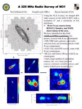
Place for logos of authors’ institutions. Radio-over-Fiber (RoF): An introductory survey. Kivilcim YUKSEL, Faculty of Engineering, Mons , kivilcim.yuksel@fpms.ac.be. Overview. Concept and Motivations Definition and Terminology Generic Architecture Methods of transmission BBoF, IFoF, RFoF

E N D
Place for logos of authors’ institutions Radio-over-Fiber (RoF): An introductory survey Kivilcim YUKSEL, Faculty of Engineering, Mons , kivilcim.yuksel@fpms.ac.be
Overview • Concept and Motivations • Definition and Terminology • Generic Architecture • Methods of transmission • BBoF, IFoF, RFoF • Optical microwave / mm-wave modulation / generation techniques • Parameters • Limitations and Issues • RoF Multiplexing Techniques • SCM, WDM • Emerging Technologies • Electroabsorbtion modulator transceiver (EAM), VCSEL, RF over MMF • Application and Deployments K.YUKSEL, RoF MODULE TITLE
Concept & Motivations: RoFuses the advantages of optical fibre to deliver radio signals to remote antenna sites for both fixed wireles access systems and mobile applications [1,2] Mobile Stations Base Station Cellular architecture Central Station Optical Fiber Large number of mobile/fixed wireless users Increased user bandwidth requirement Fixed wireless stations Base Station Increased carrier frequency more propagation loss small cell size Advantages come with the optical fiber: • Low loss, immunity to electromagnetic interference, broad bandwidth, • Transparent to modulation type and bit rate, • Large distance between Central Station and Base Station is possible, • WDM technology can be exploited. Huge number of Base Stations Need of interconnection huge number of cells (BS) This interconnection can be supported by FIBER K.YUKSEL, RoF MODULE TITLE
Definition and terminology: The technique of modulating the RF subcarrier onto an optical carrier for distribution over fiber network is known as Radio over Fiber technology [1] • Cell diameter: • Macrocell • (16-48 km) • Microcell (200m-1km) • Picocell • (10-200m) Central Station Base Station RoF Link (optical fiber) antenna downlink antenna Wireless Channel Backbone BS CS uplink MS Mobile Station (or fixed wireless access) • Complex functions are carried out here • Sensitive equipments are here in safer environment • Resources are shared among many BS • Dynamic allocation of resources is possible • The huge number of Base Stations requires the BS to be: Simple, small, low cost, easy to maintain. • Referred also Radio Access Point (RAP), or Radio Access Unit (RAU). K.YUKSEL, RoF MODULE TITLE
Generic Architecture & Principle: The basic system consists of one or more optical fibers (linking CS and BS) and laser / photodetector pairs. Power amplifier photodetector laser antenna RF in Fiber pair photodetector RF out Low Noise amplifier laser Central Station Base Station • RoF is fundamentally an analog transmission system. • RF carrier is imposed on the optical carrier, transmitted through optical fibre and converted back to the electrical domain by means of a photodetector. • The output signal from the photodetector is the copy of the RF input signal. • Antennas placed in the remote station transmit/ receive the RF signal through wireless channel. K.YUKSEL, RoF MODULE TITLE
Methods of Transmission: Three categories exist by considering the frequency of RF signal fed into the RoF link, namely RFoF, IFoF and BBoF. Photo-detector Photo-detector Photo-detector Central Station Base Station antenna RF over fibre RFoF fiber RF RF RF/Optical modulation fRF amplification fopt fRF antenna IF over fibre IFoF fIF + fLO fRF - fLO fiber IF/Optical modulation RF IF fIF RF fLO fLO fopt antenna fiber IF RF Baseband over fibre BBoF Base band Optical modulation fLO2 fLO1 fopt Note that only downlink is represented in the slide. For the uplink, reverse process is performed.
Optical wireless signal generation & Modulation: Generation / modulation techniques of microwave/mm-wave signals over optical links can be grouped into three categories [3]. Mm-wave generation & modulation techniques Intensity Modulation/ Direct Detection (IM/DD) Remote Heterodyning and Detection Harmonic up conversion FM-IM conversion Ref: [11,17] Optical FM filter system Ref: [10] Direct IM Ref: [1] Optical Frequency Multiplying (OFM) Ref: [3,5,6] Dual Mode Lasers Ref: [11] External modulation Ref: [1] Dual Laser Methods (uses 2 lasers) Double sideband suppressed carrier (2f or 4f) Ref: [18,19] Optical Frequency/ Phase Locked Loop (OFLL/OPLL) Ref: [12] Optical Injection Locking (OIL) Ref: [13,14] Optical Injection Phase Locked Loop (OIPLL) Ref: [15,16],
Intensity modulation / Direct detection (IM/DD) Central Station Base Station Direct IM laser RF signal photodetector RF out fiber bias IM by external modulator laser • Simplest solution. • Direct intensity modulation with cheap lasers is convenient for the uplink transmission to reduce system cost. • Limiting factor for Direct IM is modulation bandwidth (typically 5-10 GHz). • External modulation is used for > 10GHz. • Limiting phenomenon for External modulation is the transmission zeros due to fiber dispersion and coherent mixing of the sidebands of modulated light. External modulator RF signal bias
Remote Heterodyne Detection (RHD): Two optical signals of which the difference in optical frequency corresponds to the microwave frequency are heterodyned [5]. Central Station Base Station 1 CW photodetector RF out (fmm) fiber Mux data 2=1+fmm • Limiting factor: bandwidth of photodetectors. • Advantages: generation very high frequencies, high carrier-to-noise ratio (CNR), reduced sensitivity to chromatic dispersion. • Critical issue: instantaneous frequency difference between lasers should be stable. Methods for controlling frequency offset between the two lasers: • Optical Frequency-Locked Loop (OFLL) • Optical Phase-Locked Loop (OPLL) • Optical Injection Locking (OIL) • Optical Injection Phase-Locked Loop (OIPLL)
Harmonic Generation:(example 1: Modulation sideband technique, 2f method[5].) • One of the optical sideband components is filtered [3] • 2 strong components seperated by 2fmod are heterodyned on the photodiode to generate 2.fmod= fmm • MZM is biased so that the optical carrier and the even modulation sidebands are suppressed. • Adding data modulation is achieved by modulating one of the optical sideband components
Harmonic Generation:(example 2: Optical Frequency Multiplying[3,5,6].) [3] • The wavelength of a tunable optical source is periodically and linearly swept back and forth over a certain range with a sweep frequency (fsw). • At the remote station, a periodic optical bandpass filter is deployed. There are various options to realise the optical periodic bandpass filter: fibre Fabry-Perot filter, FBG filter, MZI filter… • Sweeping the source wavelength across N bandpass transmission peaks of the filter yields light intensity bursts on the photodiode (hence a microwave signal with fundamental frequency fmm = 2.N.fsw) • The data is intensity-modulated on the frequency-swept optical carrier by means of differentially driven M-Z modulator.
Parameters: Phase Noise and Spurious-free Dynamic Range (SFDR) are two important parameters in RoF systems. Pin Strong Signals Pin (max) 3rd Order Intermodulation SFDR Weak signal Pin (min) CNR IM3 frequency • The maximum signal power that gives the maximum dynamic range is reached at the point where noise and intermodulation are equally large. • The difference between signal noise floor / intermodulation product is called spurious free dynamic range (SFDR) [1]. K.YUKSEL, RoF MODULE TITLE
Limitations & Issues: Involving analogue modulation and detection of light, signal impairements such as noise and distortion are important for RoF systems. Central Station Base Station optical fiber antenna Wireless Channel Backbone BS CS MS Wireless channel • Multi-path fading • Distortion • Interference Fiber • attenuation • Chromatic dispersion (SMF) • Modal dispersion (MMF) Receiver • Schotky noise • Thermal noise Transmitter • Laser RIN • Phase noise • Nonlinear effects (external modulation) • Self-Phase modulation (external modulation) K.YUKSEL, RoF MODULE TITLE
RoF (optical layer) Multiplexing Techniques: Sub-carrier multiplexing (SCM) [3] [3] • A number of baseband analog or digital signals are frequency division multiplexed by using local oscillators (so called subcarriers) of different radio frequencies (fSC1, fSC2, …fSCN,). The upconverted signals are combined to drive a high speed laser source. • Services carried by different subcarriers are independent of each other, require no synchronisation. • SCM systems are more cost effective than high capacity TDM ligthwave systems. K.YUKSEL, RoF MODULE TITLE
RoF (optical layer) Multiplexing Techniques: Wavelength-division multiplexing (WDM) [4] 1 RFin1 1 EDFA fiber Mux DeMux N N RFinN • Allocation of different wavelengths to individual BS or even individual services. • Full RF bandwidth per wavelength. • Provides multi operator, flexible service provision, easy network upgrade. • Critical issue: optical spectral width of the mm wave source • Dual ring architecture using OADM proposed by Andrew [20] • Utilisation of downlink lamda in the uplink proposed K.YUKSEL, RoF MODULE TITLE Note that only downlink is represented in the slide.
Emerging Technologies:[7] Central Station Base Station (RAU) • RF over multimode fiber • Transmission of high RF carriers over MMF has been shown to be viable [9]. Motivation is to use pre-installed MMFs. • Plastic optical fiber (POF) • Might be interesting alternative in-building RoF systems due to its easy handling (easy, cheaper installation and maintenance) [5]. • Low cost lasers • VCSELs @850nm and uncooled edge emitting lasers using multi-quantum well (MQW) designs are low cost candidates for Rof systems [7]. • Electroabsorbtion modulator (EAM) transceiver • EAM replaces the laser/ photodiode pair • Acts as a photodiode for the downlink and as a modulator for the uplink • Has the potential for reducing BS cost. [21]
Today’s main Applications • In Building Coverage • Increasing quality and providing uniform distribution to densely populated indoor users (Office buildings, airports, shopping centers …) • RoF is good candidate due to low loss/ small size / low weight of optical fibre cables • Radio coverage extension for ‘Dead Zones’ Dedicated BS inside the building and distributed antenna system (DAS) [7] RoF extends the reach of an existing BS to dead spot areas [8]
Applications • Cellular Networks • RoF is a complementary solution to mobile network infrastructure. • Mobile traffic capacity can be increased in dense environments (exhibition grounds, airports, downtown street levels …) by offering greater frequency reuse [1] • Satellite Communications • Remoting of satellite earth stations from switching central or remoting antennas to suitable locations at satellite earth stations are two possible applications (with the aim of centralizing high frequency equipment) [6] • Video Distribution Systems • Cellular terrestrial video distribution (e.g.Multipoint Video Distribution Service (MDVS) ) is a promosing application [6]. • The rooftop equipment can be simlified by employing RoF techniques. • Broadband wireless access • Extention of services available in fixed broadband networks to mobile (or fixed) wireless users.
Applications fiber RF/ optical Service 1 Local base station Local base station RF/ optical converter Local base station Control station Frequency integration + conversion antenna antenna Service 2 Frequency conversion Service 1 Service 2 • Vehicle communication and Control[1] • Providing continuous mobile communication coverage on major roads for the purpose of Intelligent Transport System (ITS) • Advantage: only one antenna and RF unit mounted on the vehicule • 63-64 GHz and 76-77 GHz allocated within Europe Example services: • 5.8 GHz Electronic Tool Collection (ETC) • 2.5 GHz Vehicule infrastructure and control service (VICS) • 1.9 GHz Personal Handy –Phone System (PHS)
References • H. Al-Raweshidy, S. Komadi, ‘Radio over Fiber Technologies’, Artech House, 2002 • J.E. Mitchell, RoF technologies, e-Photon/ONE summer school presentation, Mons, 2004 • “ Radio-over-Fiber Technology for Broadband Wireless Communication Systems”, Ng’oma Anthony, PhD thesis at Eindhoven Technical University, 28 june 2005. • “Radio over Fiber Based Network Architecture”, Hong Bong Kim, PhD thesis at Berlin Technical University, October 2005. • T. Koonen and A. Ng’oma« Broadband Optical Access network and Fiber-to-the-Home. Systems Technologies and Deployment Strategies », Editor Chinlon Lin, 2006 John Wiley & Sons, Ltd. Chapter 11 • A. Ng’oma, “Design of a RoF system for Wireless LANs”, Broadband Radio @Hand, Deliverable D.6.1, 2002 • D. Wake, ‘A survey of current and emerging RoF technologies for wireless communication applications’, application note, www.microwavephotonics.com. • Hoon Kim, Samsung Electronics, ‘RoF technology for wireless communication services’, October, 2005 ,(http://www.koif.or.kr/OIW2005/proceeding-WEB/S5-02.pdf, Electronicshoonkim@ieee.org) • D.Wake et al., “32-QAM radio transmission over multimode fiber beyond the fiber bandwidth”, Int. Topical Mtg. on Microwave Photonics, MWP’01, Tech. digest pp.81-84, january 2002
References • P. Shen et al., “High-Purity Millimetre-Wave Photonic Local Oscillator Generation and Delivery”, in Proceedings of the International Topical Meeting on Microwave Photonics (MWP 2003), 2003, pp. 189-192 • D.Wake, “Optoelectronics for millimeter-wave radio over fibre systems”, in Analogue Optical Fibre Communications, B. Wilson, Z. Ghassemlooy, and I. Darwazeh, ed. (The Institute of Electrical Engineers, London, 1995) • L.N. Langley et al., “Packaged Semiconductor Laser Optical Phase-Locked Loop for Photonic Generation, Processing and Transmission of Microwave Signals”, IEEE Trans. On Microwave Theory and Techniques, vol.47, no. 7, 1257-1264, 1999 • Y.J Waen et al., “Millimeter-wave signal generation from a Monolithic Semiconductor laser via subharmonic optical injection”, IEEE Photonics Tech. Letters, vol.12, no.8, 1058-1060, 2000 • H. Furuta et al., “Optical injection locking of a 38-GHz-Band InP-based HEMT oscillator using a 1.55µm DSB-SC modulated lightwave”, IEEE Photonics Tech. Letters, vol. 11, no. 01, 19-21, 2001 K.YUKSEL, RoF MODULE TITLE
References • L.A. Johansson, and, A.J. Seed, “Millimeter-wave modulated optical signal generation with high spectral purity and wide-locking bandwidth using a fibre-integrated optical injection phase-locked loop”, IEEE Photonics Tech. Letters vol.12, no. 6, 690-692, 2000 • L.A. Johansson, and, A.J. Seed, “36 GHz 140-Mb/s RoF transmission using an optical injection phase-lock loop source”, IEEE Photonics Tech. Letters vol.12, no. 8, 893-895, 2001 • N.G. Walker et al., “Efficient millimeter-wave signal generation through FM-IM conversion in dispersive optical fibre links”, Electronics Letters, vol.28, no. 21, 2027-2028, 1992 • J.O’Reilly, and P. Lane, “Remote delivery of video services using mm-waves and optics”, JTL vol. 12, No. 2, 369-375, 1994 • C.Lim et al., “Millimeter-wave broadband fiber-wireless system incorporating baseband data transmission over fibre and remote LO delivery”, JTL, vol.18, no. 10, 1355-1363, 2000 • A. Casini, “WDM technologies for UMTS radio coverage extension by using the RoF technique”, white paper, http://www.andrew.com/search/BN_TA-100985-EN.aspx K.YUKSEL, RoF MODULE TITLE
References • 21. Trends and prospects for radio over fibre picocells Wake, D., Microwave Photonics, 2002. International Topical Meeting on Volume , Issue , 5-8 Nov. 2002 Page(s): 21 - 24 Note: The frequencies of the radio distributed by Rof systems span a wide range and depend on the nature of the applications. In this presentation the terms microwave and Radio frequency (RF) are used interchangeably when referring to all the electrical signals generated at the BS of the RoF system. K.YUKSEL, RoF MODULE TITLE