Download

1 / 44
440 likes | 585 Views
Preferred Utilities Manufacturing Corp. UtilitySaver Overview. Preferred Utilities Manufacturing Corporation 31-35 South St. • Danbury • CT www.preferred-mfg.com. UtilitySaver Burner Control. Introduction Energy Savings Fuel Savings Electrical Savings System Composition

E N D
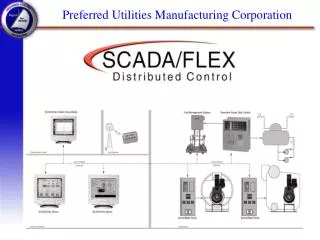
Preferred Utilities Manufacturing Corp UtilitySaver Overview Preferred Utilities Manufacturing Corporation 31-35 South St. • Danbury • CT www.preferred-mfg.com
UtilitySaver Burner Control • Introduction • Energy Savings • Fuel Savings • Electrical Savings • System Composition • UtilitySaver Panel • Oxygen Analyzer • Actuators • Variable Frequency Drive • Installation • Summary
UtilitySaver Burner Control The UtilitySavertm uses a single PCC-III Controller to provide state of the art burner control. The package includes firing rate control with both oxygen trim and variable speed fan combustion air flow control. UtilitySaverfuel and electrical savings can pay for the installed system in two years or less.
UtilitySaver Burner Control Includes: • UtilitySaver Panel • Oxygen Analyzer Kit • Boiler Efficiency Kit • Actuator Kit • Jackshaft and UtilitySaver Damper • Variable Frequency Drive (VFD) Kit • Installation Materials and Supervision!
UtilitySaver Burner Control • Introduction • Energy Savings • Fuel Savings • Electrical Savings • System Composition • UtilitySaver Panel • Oxygen Analyzer • Actuators • Variable Frequency Drive • Installation • Summary
Energy Savings Fuel Savings + Electrical Savings
Fuel Savings: Seasonal Air Density and Humidity Changes Fuel Pressure and Temperature Changes Fuel Btu and Viscosity Variations Worn Linkage Components (Hysteresis) Electrical Savings: Minimizing Damper Pressure Drop - damper is 100% open for maximum kWh savings, (Partially closed at low fire to maximize burner turndown) Oversized Fans Oversized Motors Partially Loaded Boilers Energy Savings
Natural gas fired Operating 365 days / year & 24 hours / day Electric Cost - 7.5 cents / kWh Fuel Cost - $4.5/k ft3 Oxygen Reduction - 1.5% Wet Based on: ASME “by losses” boiler efficiency calculations. Industry leading manufacturer motor energy data. 600 Bhp Boiler 125 psi Steam Energy Savings Conservative $13,700 per Year
Unique Energy Savings Tool • Savings Estimate Based on: • Boiler size • Motor HP • Air Damper Type • Current O2 Level • Projected O2 Level • Flue Gas Temperature • Seasonal Loading Data • Fuel Cost • Electrical Cost
Variations in Air Composition • “Standard” air has 0.0177 LB. O2 per FT3 • Hot, humid air has less O2 per cubic ft • 20% less at 95% RH, 120OF, and 29.9 mm Hg • Dry, cold air has more O2 per cubic ft • 10% more at 0% RH, 32OF, and 30.5 mm Hg • Standard Combustion controls must: • Allow at least 20% extra excess air because of the change in air density.
Variations in Air Composition At these ambient conditions the burner has extra O2 & N2
HP Savings Combustion Air Fan Hp Savings Damper Control Motor Power(HP) Input, % Full Load Variable Speed Control Combustion Air Flow, %Full Load Reference 1
UtilitySaver Burner Control • Introduction • Energy Savings • Fuel Savings • Electrical Savings • System Composition • UtilitySaver Panel • Oxygen Analyzer • Actuators • Variable Frequency Drive • Installation • Summary
The UtilitySaver Controller Right For the Job...
The UtilitySaver Panel Measured Flue Gas Oxygen Firing Rate % (shown) Steam PSIG Steam PSIG SP Oxygen % Oxygen SP Oxygen Trim % VFD Speed Fuel Valve Position Air Damper Position Boiler Efficiency Flue Gas Oxygen Setpoint Firing Rate Organized, simple and to the point local operation
The UtilitySaver Panel • Enclosure - • Nema 12, 16 H x 14 W x 10 D • Controller - • PCC-III with “Z”, and “G” Option Boards. • Components - • VFD / Flame Safeguard interface relays • 24Vac power supply transformer for DM-1E Actuators • Shielded cable for field wiring
The UtilitySaver Controller • PCC-III-ZG00 • “Z” Option Board, Oxygen Analyzer • “G” Triac Outputs to Drive Electric Actuators • Constructed For Boiler Front Mounting • Intuitive Operation • Flexible, powerful blockware control logic • Built In Boiler Efficiency • F(x) Characterizers with “Learn” Mode • Commissioning Tools
UtilitySaver Features • Minimizing Damper Pressure Drop • Damper is 100% open for maximum kWh savings, (Partially closed at low fire to maximize burner turndown) • Fuel-Air Lead-Lag With Cross-Limiting • On a load increase, Air increases first. On a load decrease, Fuel decreases first. • Minimizes excess air during normal firing, and increases excess air during a load change for safety. • Excess air is limited during load changes for flame stability.
UtilitySaver Features • Independent Fuel-Air Ratio Curves • PCC-III "Learn" mode • Rapid, error free burner fuel-air ratio curve setup, with easy "Store" pushbutton operation. • Safety • Low flue gas oxygen trips the burner after an adjustable time delay. • VFD speed and actuator position feedbacks are continuously monitored. Burner trips after an adjustable time delay if any are out of position. • Real Time Boiler Efficiency • Continuous Oxygen Analyzer Diagnostics
Touch Screen Options 10 inch
Only one conduit to stack. In-Situ Oxygen Analyzer Field replaceable detector No separate analyzer, one less item to mount
In-Situ Oxygen Analyzer • Proven Reliable • Zirconia Oxide Sensor • No Reference Air • The probe uses ambient air as a reference. • Competitors use instrument air and run the risk of element cracking due to water • Automated, menu driven pushbutton calibration. • Automatic impedance checking • Alarms when time to recalibrate
Oxygen Analyzer Kit • Model ZP Oxygen Sensor, 20” Standard • Reliable Zirconia Oxide Cell • 60 ft ZP Cable • Mounting Hardware included
Boiler Efficiency Kit • PCC-III Controller calculates the ASME “by losses” method efficiency in real time. Kit Includes: • Flue Gas Temperature Assembly, Type J, p/n 104087C, with mounting flange • 60 feet of shielded type J T/C extension cable
Actuator Kit • Two (2) DM-1E Actuators are Included: Jackshaft & Damper • Torque: 150 in-lbs • Rotation: 90° travel in 30 seconds • Aux. Switches: Integral 2 SPDT • Position Feedback: 600 ohm • Power Supply: 24 Vac • (2)Linkages, (3)Lever Arms, (1)Mounting Bracket
Alternate Actuators • R-AL : 100 lb Linear Thrust • 1730: 1000 in-lb Torque • UP10 Pneumatic: 1080 in-lb Torque • I/P Kit to interface to Existing Pneumatic Jackshaft Actuator • Pot Box, if Existing Actuator doesn’t have Feedback
Variable Speed Fan Air Flow Control • Variable Speed Drive (VSD) - The UtilitySaver package includes a full featured, quality drive. • Nema 12 Packaging - for worry free boiler room installation • Built in “DC Link” line reactor - for reduced electrical system harmonics distortion • “Soft Turn On” IGBT transistors - for reduced motor stress (lower peak voltages)
VSD Parts & Theory • 5 Parts to a VSD • Rectifier • DC “Link” line reactor • Intermediate Circuit • Inverter (IGBT = Insulated Gate Bipolar Transistor) • Control & Regulation
Pulse Width Modulation (PWM) • On or Off, voltage does NOT modulate. • PWM allows IGBT’s to run cool for long life, so better VSD’s use PWM. • However, PWM dV/dt causes spike voltages
“Soft Turn On” IGBTs • dv/dt - Change in Voltage over Time • Competitor’s Drives - up to 3500V/us • UtilitySaver Drive - 900V/us • Due to Patented “Soft Turn On” IGBT’s • Lower Peak Voltages Extend Motor Insulation Life • 460V, 75 Hp motor: 815V peak for 50 ft cable
Automatic Over Ramp Protection • The UtilitySaver VFD will not trip when given a “STEP” speed increase of 0 to 100 % • The drive automatically limits the rate of fan speed increase to that which will prevent an over current trip. • Other drives do not have this feature. Other drives may trip if the speed is increased too quickly.
UtilitySaver Burner Control • Introduction • Energy Savings • Fuel Savings • Electrical Savings • System Composition • UtilitySaver Panel • Oxygen Analyzer • Variable Frequency Drive • Actuators • Installation • Summary
UtilitySaver Installation • Sole Source Responsibility • Locate all device mounting locations • Install Oxygen Sensor & Flue Gas T/C. • Install and adjust damper linkage, and stroke actuators. • Run conduit and wire to field devices, existing motor starter, motor and control panels. • Commission UtilitySaver package for optimum burner performance • Train Owners Operators for proper operation
UtilitySaver Burner Control • Introduction • Energy Savings • Fuel Savings • Electrical Savings • System Composition • UtilitySaver Panel • Oxygen Analyzer • Actuators • Variable Frequency Drive • Installation • Summary
Experience Preferred Instruments has 25 years of Combustion Control Experience with… • A Third Generation Digital Controller • Over 1000 Boiler Control System Installations • 2400 PCC II/III Controllers Installed Exclusivelyin Combustion Control Applications • 45 SCADA/Flex Projects • 640 Burner Projects
Experience Compatible with other products from Preferred Instruments... • SCADA/Flex Remote Operator Stations • BMS Logic+ Burner Management Systems • Boiler Sequencing, Lead / Lag Systems • Feedwater Control Systems • Draft Control Systems • Balance Of Plant (BOP) Systems
Summary UtilitySaver …... • Excellent Annual Savings • Savings from Both oxygen trim and variable speed fan combustion air flow control • Field proven and feature rich PCC-III Controller • Backed by over a thousand package boiler control installations • Single Source Responsibility • Complete Material and Installation
Preferred Utilities Manufacturing Corp Preferred Utilities Manufacturing Corporation 31-35 South St. • Danbury • CT T: (203) 743-6741 • F: (203) 798-7313 www.preferred-mfg.com • info@preferred-mfg.com