Download

1 / 52
530 likes | 557 Views
Learn about magnetic disks, storage mechanisms, access methods, and disk failure rates. Explore how to optimize data retrieval and enhance disk reliability in computer architecture.

E N D
HARD DISKS AND OTHER STORAGE DEVICES Jehan-François PârisSpring 2015
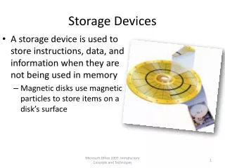
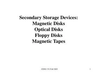
Magnetic disks (I) Sole part of computer architecture with moving parts: Data stored on circular tracks of a disk Spinning speed between 5,400 and 15,000 rotations per minute Accessed through a read/write head
Magnetic disks (II) Servo Platter Arm R/W head
Magnetic disks (III) Data are stored into circular tracks Tracks are partitioned into a variable number of fixed-size sectors Outside tracks have more sectors than inside tracks Ifdisk drive has more than one platter, all tracks corresponding to the same position of the R/W head form a cylinder
Seagate ST4000DM000 (I) • Interface: SATA 6Gb/s (750MB/s) • Capacity: 4TB • Cache: 64MB multisegmented • Seek Average • Read: < 8.5ms • Write: <9.5ms • Average data rate: 146 MB/s (R/W) • Maximum sustaineddata rate: 180MB/s
Seagate ST4000DM000 (II) • Number of platters: 4 • Number of heads: 8 • Bytes per sector: 4,096 • Irrecoverable readerrors per bit read: 1 in 1014 • Power consumption • Operating: 7.5W • Idle: 5W • Standby & Sleep: 0.75W
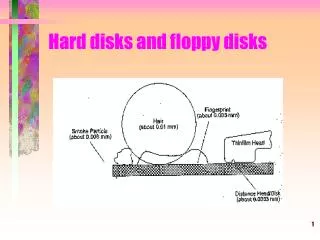
Sectors and blocks • Sectors are the smallest physical storage unit on a disk • Fixed-size • Traditionally 512 bytes • Separated by intersector gaps • Blocks are the smallest transfer unit between the disk and the main memory
Magnetic disks (III) Disk spins at a speed varying between 5,400 rpm (laptops) and 15,000 rpm (Seagate Cheetah X15, …) Accessing data requires Positioning the head on the right track: Seek time Waiting for data to reach the head On the average half a rotation Transferring the data
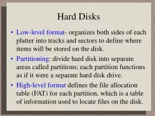
Accessing disk contents Each block on a disk has a unique address Normally a single number Logical block addressing (LBA) Standard since 1996 Older disks used a different scheme Cylinder-head-sector Exposed disk internal organization Can still map old CHS triples onto LBA addresses
Disk access times Dominated by seek time and rotational delay We try to reduce seek times by placing all data that are likely to be accessed together on nearby tracks or same cylinder Cannot do as much for rotational delay
Seek times (I) • Depend on the distance between the two tracks • Minimal delay for • Seeks between adjacent tracks • Track to track (1-3 ms) • Switching between tracks within the same cylinder • Worse delay for end to end seeks
Seek times (II) 3 to 5x Seek time x Track to track End to end
Rotational latency • On the average half a rotation • Same for read and writes • One and half rotations for write/verify
Transfer rate (I) • Burst rate: • Observed while transferring a block • Highest for blocks on outside tracks • More of them on each track • Sustained transfer rate: • Observe red while reading sequential blocks • Lower
Transfer rate (II) • Actual transfer rate
File B0 B1 B2 B3 B4 B5 B6 … Double buffering (I) • Speeds up handling of sequential file Processed by DBMS Buffers B1 B2 In transfer
File B0 B1 B2 B3 B4 B5 B6 … Double buffering (II) • When both tasks are completed Processed by DBMS Buffers B3 B2 In transfer
The five minute rule • Jim Gray • Keep in memory any data item that will be used during the next five minutes
The internal disk controller Printed circuit board attached to disk drive As powerful as the CPU of a personal computer of the early 80's Functions include Speed buffering Disk scheduling …
Disk failure rates Failure rates follow a bathtub curve High infantile mortality Low failure rate during useful life Higher failure rates as disks wear out
Disk failure rates (II) Failurerate Wearout Infantilemortality Useful life Time
Disk failure rates (III) Infant mortality effect can last for months for disk drives Cheap SATA disk drives seem to age less gracefully than SCSI drives
The Backblaze study Reported on the disk failure rates of more than 25,000 disks at Backblaze. Their disks tend to fail at a rate of 5.1 percent per year during their first eighteen months 1.4 percent per year during the next eighteen months 11.8 percent per year after that
MTTF Disk manufacturers advertise very highMean Times To Fail (MTTF) for their products 500,000 to 1,000,000 hours, that is,57 to 114 years Does not mean that disk will last that long! Means that disks will fail at an average rate of one failure per 500,000 to 100,000 hours duringtheir useful life
More MTTF Issues (I) Manufacturers' claims are not supported by solid experimental evidence Obtained by submitting disks to a stress test at high temperature and extrapolating results to ideal conditions Procedure raises many issues
More MTTF Issues (II) Failure rates observed in the field aremuch higher Can go up to 8 to 9 percent per year Corresponding MTTFs are 11 to 12.5 years If we have 100 disks and a MTTF of 12.5 years, we can expect an average of 8 disk failures per year
What about flash? • Widely used in flash drives, most MP3 players and some small portable computers • Several important limitations • Limited write bandwidth • Must erase a whole block of data before overwriting any part of it • Limited endurance • 10,000 to 100,000 write cycles
Flash drives • Widely used in flash drives, most MP3 players and some small portable computers • Similar technology as EEPROM • Three technologies: • NOR flash • NAND flash • Vertical NAND
NOR Technology • Each cell has • one end connected straight to ground • the other end connected straight to a bit line • Longest erase and write times • Allow random access to any memory location • Good choice for storing BIOS code • Replace older ROM chips
NAND Technology • Shorter erase and write times • Requires less chip area per cell • Up to ten times the endurance of NOR flash. • Disk-like interface: • Data must be read on a page-wise basis • Block erasure: • Erasing older data must be performed one block at a time • Typically 32, 64 or 128 pages
Vertical NAND Technology • Fastest
The flash drive controller • Performs • Error correction • Higher flash densities result in many errors • Load leveling • Distribute writes among blocks to prevent failures resulting from uneven numbers of erase cycles • Flash drives works best with sequential workloads
Performance data • Widely vary between models: • One random pair of specs: • Read Speed 22MBps • Write Speed 15MBps
RAID level 0 No replication Advantages: Simple to implement No overhead Disadvantage: If array has n disks failure rate is n times the failure rate of a single disk
RAID levels 0 and 1 RAID level 0 Mirrors RAID level 1
RAID level 1 Mirroring Two copies of each disk block Advantages: Simple to implement Fault-tolerant Disadvantage: Requires twice the disk capacity of normal file systems
RAID level 4 (I) Requires N+1 disk drives N drives contain data Individual blocks, not chunks Blocks with same disk address form a stripe x x x x ?
RAID level 4 (II) Parity drive contains exclusive or of theN blocks in stripe p[k] = b[k] b[k+1] ...b[k+N-1] Parity block now reflects contents of several blocks! Can now do parallel reads/writes
RAID levels 4 and 5 Bottleneck RAID level 4 RAID level 5
RAID level 5 Single parity drive of RAID level 4 is involved in every write Will limit parallelism RAID-5 distribute the parity blocks among the N+1 drives Much better
The small write problem Specific to RAID 5 Happens when we want to update a single block Block belongs to a stripe How can we compute the new value of the parity block p[k] b[k] b[k+1] b[k+2] ...
First solution Read values of N-1 other blocks in stripe Recompute p[k] = b[k] b[k+1] ...b[k+N-1] Solution requires N-1 reads 2 writes (new block and new parity block)
Second solution Assume we want to update block b[m] Read old values of b[m] and parity block p[k] Compute p[k] = new b[m] old b[m] old p[k] Solution requires 2 reads (old values of block and parity block) 2 writes (new block and new parity block)
Other RAID organizations (I) RAID 6: Two check disks Tolerates two disk failures More complex updates
Other RAID organizations (II) RAID 10: Also known as RAID 1 + 0 Data are striped (as in RAID 0 or RAID 5) over pairs of mirrored disks (RAID 1) RAID 1 RAID 1 RAID 1 RAID 1 RAID 0
Other RAID organizations (III) Two dimensional RAIDs Designed for archival storage Data are written once and read maybe(WORM) Update rate is less important than High reliability Low storage costs