Investigating RF Power Loss Properties in Relation to Magnetic Field Strength and Heating Efficiency
110 likes | 222 Views
This study aims to measure RF power loss properties as a function of magnetic field strength ( B ) under constant safety factor ( q ). It explores how RF power loss scales with ( B ), assesses parametric decay instability (PDI) losses against ( B ), and analyzes the effects of fast wave propagation on surface waves. The experiment provides critical insights for improving heating efficiency in plasma confinement, with results applicable to future higher magnetic field regimes in stellarator and tokamak designs, enabling optimized wave propagation and reduced losses.

Investigating RF Power Loss Properties in Relation to Magnetic Field Strength and Heating Efficiency
E N D
Presentation Transcript
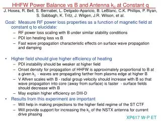
HHFW Power Balance vs B and Antenna k|| at Constant qJ. Hosea, R. Bell, S. Bernabei, L. Delgado-Aparicio, B. LeBlanc, C.K. Phillips, P. Ryan, S. Sabbagh, K. Tritz, J. Wilgen, J.R. Wilson, et al. Goal: Measure RF power loss properties as a function of magnetic field at constant q to elucidate: • RF power loss scaling with B under similar stability conditions • PDI ion heating loss vs B • Fast wave propagation characteristic effects on surface wave propagation and damping • Higher field should give higher efficiency of heating • PDI instability should be weaker at higher field • Onset density for propagation of HHFW is approximately proportional to B at a given k|| - waves are propagating farther from plasma edge at higher B • V Alfven scales with B - radial group velocity should increase with B so that wave propagation into core (away from surface) is faster - surface fields should decrease with B • May explain higher efficiency on DIII-D • Results from this experiment are important • Will help in making projections to the higher field regime of the ST CTF • Will provide support for increasing the k|| of the NSTX antenna for current drive phasing XP617 W-P ET
0.20 0.15 PDI Losses Are Evident at Both k|| Values - Significant RF Power is Required to Sustain the Large Temperature Difference Between the Edge Ions and Electrons • Edge ion heating via parametric decay waves accounts for a substantial • amount of RF power loss which increases somewhat with wavelength - • 16%/23% loss for 14 m-1/-7 m-1 T.M. Biewer et al., Physics of Plasmas 12 (2005) 056108
Propagation of fast wave begins at lower density for lower k|| Propagating k vs density and k|| with B = 4.5kG k|| = 3m-1 7m-1 14m-1 Density onset is function of ~ B*k||2 • Propagation is very close to wall at 7m-1 and on the wall at 3m-1 • Losses in surface should be higher for lower k||
B = 3 kG B = 5.5 kG VGpar VGpar VGper VGper This proposal is to study heating efficiency/power loss over the widest magnetic field range possible • 3 kG @ 400 kA and 5.5 kG @ 730 kA • Constant q is desired to control stability • Propagation onset density decreases a factor of two at the lower field • for both 7m-1 and 14m-1 • Surface losses should increase substantially at the lower field - even at 14m-1 • Perpendicular group velocity also decreases by a factor of ~ 2 - surface • fields should be enhanced further increasing edge losses • PDI losses can be expected to increase substantially at the lower field
Comparison of Thomson scattering measurements vs k|| at 5.5 kG and 3.0 kG Vertical Instability 3.0 kG 5.5 kG k|| = 14 m-1 7 m-1 -3 m-1 • Te(0) is much larger at B = 5.5 kG for k|| = 7 m-1, Teo is also longer • Heating at -3 m-1 is still small at 5.5 kG • Vertical instability seriously affects the results at 3 kG for time > about 0.23 sec
Comparison of Thomson scattering measurements vs k|| at 3.0 kG and 3.5 kG Vertical Instability 3.0 kG k|| = 14 m-1 7 m-1 -3 m-1 3.5 kG • Te(0) is significantly larger at B = 3.5 kG for k|| = 14 m-1 • Instability still seriously affects the results at 3.5 kG for time > about 0.25 sec
B = 3.5 kG B = 5.5 kG TiHOT Time (sec) Time (sec) B = 3.0 kG ERD TiHOT vs Band k|| at R = 145 cm Helium, PRF = 2 MW TiHOT k|| = -3m-1 k|| = -7m-1 k|| = 7m-1 k|| = 14m-1 • Reduction in TiHOT at higher field, • especially at k|| = 14 m-1 • Reduction at lower field perhaps due to • hot ion loss or vertical instability Time (sec)
RF Probe Signals are a strong function of k|| BRF (au) B= 5.5 kG PRF = 2 MW k|| = -3m-1 -7m-1 14m-1 Time (sec) • BRF at Bay J midplane increases by a factor of ~ 3 for a decrease in • k|| from 14m-1 to -3m-1 • This could give rise to around an order of magnitude increase in structure/sheath losses • Fluctuation level at high power appears to be large
Good Heating Observed for k|| = -7m-1 at B = 5.5 kG -- Teo > 3.6 keV for PRF = 2 MW TS fOSXR ERD • TiHOT and Ti1G evolve somewhat during pulse • - but do not see core collapse • BRF also evolves smoothly (0.012 - 0.016) • Fast time behavior of Te(0) is indicated by • fast OSXR diagnostic • MHD is observed at the core temperature • collapse
Expected Results • Heating efficiencies vs B for 14 m-1, -7 m-1 (co CD) and 7 m-1 ( phasing) • Core heating from EFIT W • Core electron heating from Thomson scattering • Edge heating/power loss • Edge ion heating from edge rotation diagnostic • Edge electron heating from Thomson scattering • Behavior of PDI characteristics and induced losses with field • Plasma profiles , core and edge, for permitting predictions of wave propagation and damping characteristics and of PDI produced losses • Relative surface wave amplitude for comparison to surface power loss for the explored conditions • Ceramic gap RF emission for the explored conditions
Planned Analysis • Calculation of and W for EFIT W to obtain percent PRF deposited • Calculation of e and We for Thomson scattering We to obtain PRF delivered to electrons • Compare efficiencies for the two field cases • Analysis of wave propagation and damping characteristics from onset density into the core of plasma - along field and perpendicular directions of the ray path, and including collisions - for predicting surface losses • Development of predictions for PDI losses • Projection of heating efficiency expected at 10 kG, with and without PDI present, to compare with DIII-D results and for higher field ST devices Preliminary Conclusions • HHFW heating decreases with decreasing k|| and improves with B • PDI edge heating is a relatively weak function of B except for 14 m-1 • Edge RF B field is strongly dependent on k|| suggesting surface waves • could contribute significantly to RF power losses • In future, we need to determine RF B toroidally and poloidally as function • of B and look at FFT spectra to evaluate edge turbulence • We should increase current drive k|| to improve CD efficiency • Also, preliminary analysis suggests that increasing the frequency would • greatly reduce the PDI heating