Download
1 / 53
530 likes | 655 Views
MUCH Electronics: Indian Effort Physics with FAIR: Indian Perspective March 8 to 10, 2010. Susanta K Pal Variable Energy Cyclotron Centre 1/AF, Bidhan Nagar, Kolkata – 700 064, India. MUCH Electronics: Indian Effort. Introduction : PMD from SPS to RHIC and LHC

E N D
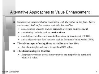
MUCH Electronics: Indian Effort Physics with FAIR: Indian Perspective March 8 to 10, 2010 Susanta K Pal Variable Energy Cyclotron Centre 1/AF, Bidhan Nagar, Kolkata – 700 064, India Physics With FAIR: Indian Perspective, Susanta K Pal
MUCH Electronics: Indian Effort • Introduction : PMD from SPS to RHIC and LHC • Electronics and Readout for STAR • FEE Development • TRIGGER • DAQ • Electronics and Readout for ALICE • FEE Development • TRIGGER • LV Distribution • MUCH Electronics: • Understanding of Electronics • FEE • RORC • INDIAN Contribution to CBM MUCH Electronics • Remarks Physics With FAIR: Indian Perspective, Susanta K Pal
Introduction: Preshower Photon Multiplicity Detector (PMD) • At SPS (WA93/WA98 Experiments) • Scintillator pads with wavelength shifting fibres using image intensifier + CCD camera systems readout. 3 X0 thick Lead converter • Scintillator pads of size: 10, 15, 20, 25 mm2 • WA93 (1990-92) : 8000 pads covering 3m2 • WA98 (1993-96): 53000 pads covering 21m2 At RHIC and LHC (STAR and ALICE experiments) Honeycomb gas proportional counter with copper honeycomb cathode, gold plated tungsten wire anode, anode signal processing using GASSIPLEX and MANAS,3X0 thick lead converter. STAR : 83,000 cells, 1 sq.cm cross-section, 8mm gas depth.Installed in 2002 and data taking is going on ALICE : 220,000 cells, 0.22 sq.cm cross-section, 5mm gas depth. Installed in 2008 and data taking is going on PMD probes thermalisation (flow), phase transition (multiplicity fluctuation), Chiral symmetry restoration (charged-neutral fluctuation) SPS RHIC LHC CBM Physics With FAIR: Indian Perspective, Susanta K Pal
WA98 PMD 53000 pads, 21 sq.m. area Physics With FAIR: Indian Perspective, Susanta K Pal
PMD @ STAR(Identical with ALICE PMD TDR design) • Preshower Detector with fine granularity • Two planes: Veto + Pre-shower • h Coverage: 2.3 – 3.9 • Total no. of cells: 82,944 • Distance from vertex: 550cm • Cell cross section: 1.0 cm2, depth: 0.8 cm • Readout: GASSIPLEX 0.7-3 + C-RAMS • 24 Supermodules, 144 Unit modules • Rhombus geometry of unit modules PMD front view Joining of two halves Physics With FAIR: Indian Perspective, Susanta K Pal
Basic design of PMD 70-pin connector FEE board With 4-Gas Chips Top PCB Bottom PCB Copper honeycomb Physics With FAIR: Indian Perspective, Susanta K Pal
BLOCK DIAGRAM for READOUT SCHEME at STAR CRAMS GAS-4 BOARDS FEE BUFFER DETECTOR Clear, TRANSLATOR SEQUENCER CLK T/HOLD • Detector signals processed by GASSIPLEX (16 channel Analog Signal Processor) chips. • Entire Readout consists of 48 chains for 82944 channels. • Each Chain consists of : • Translator ( NIM to + 2.5 V Levels) for control Signals • 27 No. Gas-4 Boards (1728 channels) • Buffer to carry Analog Mux Signal to Digitizer(CRAMS ,SEQ) Physics With FAIR: Indian Perspective, Susanta K Pal
BLOCK DIAGRAM OF GASSIPLEX Technology : Alcatel-Mietec-0.7m Silicon area : 3.63 x 4 = 14.5 mm2 SPECIFICATIONS Peaking time 1.2 s Peaking time adjust. 1.1 to 1.3 s Noise at 0 pF 530 e- rms Noise slope 11.2 e- rms/pF Dynamic range ( + ) 560 fC (0 to 2 V) Dynamic range ( - ) 300 fC (0 to –1.1 V) Gain 3.6 mV/fC Non linearity 2 fC Baseline recovery .5% after 5 s Analog readout speed 10MHz (50 pF load) Power consumption 8mW/chan. at 10 MHz Output Temp Coeff. 0.05 mV/0C Physics With FAIR: Indian Perspective, Susanta K Pal
PCB LAYOUTS : GAS -4 Boards Gas-4(N) Gas-4(M) Buffer Protection Board Translator Physics With FAIR: Indian Perspective, Susanta K Pal
2000 GAS-4 boards assembled at KHMD BANGALORE 8 –10 % Gas-4 Boards were found to be faulty after assembly. 3000 Protection Boards assembled and tested at VECC 80 Translator boards fabricated and tested at VECC 80 Buffer boards fabricated tested at VECC Physics With FAIR: Indian Perspective, Susanta K Pal
Translator,Gas-4 board, Buffer CRAMS C-RAM Sequencer Pedestal for 1728 channels Physics With FAIR: Indian Perspective, Susanta K Pal
PMD01 PMD02 VME CPU CPU CRAMS CRAMS CRAMS CRAMS CRAMS CRAMS Sequencer Sequencer VME Crate-1 VME Crate-2 VME Experimental Site Ethernet SW NIM DAQ Room PMD03 NIM CPU NIM PMD DAQ SETUP at STAR Arrangement of C-RAMS RACK-1 Physics With FAIR: Indian Perspective, Susanta K Pal
Most Crucial Challenges faced : To Design the Trigger Logic - L0 of STAR is after 1 us -Peaking time of Gassiplex is 1.2 us Solution: - Use PreTrigger form ZDC of BBC with L0 - Separate Trigger Logic for PMD was designed in tune with STAR main Trigger Physics With FAIR: Indian Perspective, Susanta K Pal
PMD TRIGGER SETUP @ STAR Experiment Physics With FAIR: Indian Perspective, Susanta K Pal
Photon Multiplicity Detector (PMD) in STAR STAR PMD running since January, 2004 Physics With FAIR: Indian Perspective, Susanta K Pal
PMD in ALICE @ LHC PMD Physics With FAIR: Indian Perspective, Susanta K Pal
PMD in ALICE , coverage2.3-3.5, 2 Distance from IP 361.5 cm Cell cross-section 0.22 cm2 Cell depth 0.5 cm No. of UMs 48 No. of cells in a UM4608 No. of HV channels48 Signal processing MANAS Total Cells 221184 Physics With FAIR: Indian Perspective, Susanta K Pal
Electronics Architecture for PMD in ALICE • 3 Level hierarchy • - Integrated preamplifiers (16 channels per chip) • MANAS • Embedded read-out daugther board with coding and zero suppression (64 channels) • MANU + MARC (digital asic) • Concentrator and processing board • CROCUS Physics With FAIR: Indian Perspective, Susanta K Pal
CAL T/H CLR CLK-1 MANAS CLK-2 TOKEN-IN CONTROL SIGNALS AD 7476 D ETECTOR Analog Out KM 4110 ADC 0 12 Bit ADC LINK PORT MANAS MARC CS DATA SIGNALS, LPCLK CLK-ADC MANAS TOKEN-OUT AD7476 Analog Out ADC 1 12 Bit ADC KM 4110 MANAS DIGITAL BUS-LVTTL FEE • Features • 64 cell inputs • Embedded on the chambers • On-boardanalog to digital conversion • 12 bit / 32 µs for 64 channels • Digital communication withupperlevel • 20 Mbyte/s • Zero suppression MANAS MARC • Main Components: • MANAS (Multiplexed-Analog-Signal-Processor ) • MARC ( Muon-Arm-Readout-Chip ) • 3. ADC (Analog to Digital Converter ) Physics With FAIR: Indian Perspective, Susanta K Pal
MARC block diagram. Timing sequence of the control signals for the MANAS-16 multiplexed readout. Physics With FAIR: Indian Perspective, Susanta K Pal
Readout Boards Using MANAS ( 4-Chips: 64 Channels) 4000 Boads FEE Board-Top side 6 layer, Size 70*24 m 1 mm thick PCB FEE-Board (Bottom side) LVDS LVTTL Translator 4 layer boards- Size 63*36 mm 1mm thick PCB Bridge Board (Digital buffer) Physics With FAIR: Indian Perspective, Susanta K Pal
12 boards on UM, Back plane PCB UM-long FEE FEE LVTTL bus LV TB BB Flexible link Patch Cable Vertical Mounting of Boards Physics With FAIR: Indian Perspective, Susanta K Pal
CROCUS Structure TO 10 PATCH BUS J T A G J T A G J T A G J T A G J T A G J T A G J T A G J T A G J T A G J T A G Front board Front board Front board Front board Front board DSP Analog Device 21160 BGA 400 Pins at 80Mhz Front board :UP TO 10 PATCHconnected vialinkport and serial port 2 DSPs analog Devices From 1 to 5 front boards Concentrator board : J T A G J T A G • 2 DSPs analog Devices, driving the front board EEPROM • 2 DSPs for the event building, the monitoring, the debug. FPGA SIU Interface SIU INTERFACE BOARD Debug TO VME DISPATCHING • 1 FPGA for the trigger and board control FPGA TRIGGER Trigger & config • 1 FPGA to make the interface with the SIU • 1 SIU interface board DDL to RORC Physics With FAIR: Indian Perspective, Susanta K Pal
Connection of a Chain Total no of cells : 221184 Total no of Modules : 48 1 module = 4608 cells. 1 CROCUS - 50 Patch Buses 6 CROCUS – 300 Patch Buses Patch Bus 2 *32 cells CHAIN Translator DDL 8.5 mt LDC CROCUS 40 meters LVDS LINKPORTS TRIGGER BUSY, and L0 CTP LTU GDC TRIGGER L0 BUSY VME TRIGGER DISPATCHING Physics With FAIR: Indian Perspective, Susanta K Pal
Chain 5 Chain 6 Chain 4 LV In Chain 1 Chain 2 Chain 3 ALICE LV Distribution Filter-Box 3-phase supply 3486- 48V supply A3009B LVDB With sense Wire +2.5V -2.5V +3.3V EASY 3000 DC-DC Converter One detector module = (72 FEE) i.e. 6 chains with 12 FEE boards per chain ALICE-FEE having 6chains in a module
DAQ-ARCHITECTURE Physics With FAIR: Indian Perspective, Susanta K Pal
Timing of the acquisition Sequence Physics With FAIR: Indian Perspective, Susanta K Pal
Contribution to STAR and ALICE • PMD with Full Electronics • Readout Concentrator Board • Integration of PMD DAQ with main STAR and ALICE DAQ • EPICS based Detector control system at STAR • PVSS based Detector Control System integrated with main ALICE DCS • Tier2 for LHC Grid for processing large volume of data Next, FOR MUCH Electronics at CBM Experiment Physics With FAIR: Indian Perspective, Susanta K Pal
assume archive rate: few GB/sec 20 kevents/sec Hadrons offline offline >10 AGeV trigger ondisplaced vertex trigger <10 AGeV trigger drives FEE/DAQarchitecture Leptons trigger μ+μ- trigger e+e- μidentification offline for e+e- trigger for μ+μ- ? trigger on high pte+ - e- pair Photons offline ? Data Acquisition at CBM(FAIR) • measure: π, K • measure: K, , , , • measure: D0, D±, Ds, c • measure: J/, ' e+e- or μ+μ- • measure: , , e+e- or μ+μ- • measure: γ From Walter F.J. Mueller’s lecture Physics With FAIR: Indian Perspective, Susanta K Pal
Buffer Conventional FEE-DAQ-Trigger Layout in HEP Especially instrumented detectors Detector L0 Trigger fbunch Trigger Primitives Dedicated connections FEE Cave Limited capacity Shack L1 Accept DAQ Modest bandwidth L2 Trigger L1 Trigger Limited L1 trigger latency Specialized trigger hardware Archive From Walter F.J. Mueller’s lecture Physics With FAIR: Indian Perspective, Susanta K Pal
Limits of Conventional Architecture Decision time for first level trigger limited. typ. max. latency 4 μs for LHC Not suitable for complex global triggers like secondary vertex search Only especially instrumented detectors can contribute to first level trigger Limits future trigger development Large variety of very specific trigger hardware High development cost Physics With FAIR: Indian Perspective, Susanta K Pal
Typical Self-Triggered Front-End Use sampling ADC on each detector channel running with appropriate clock • Average 10 MHz interaction rate • Not periodic like in collider • On average 100 ns event spacing a: 126 t: 5.6 a: 114 t: 22.2 amplitude Time is determined to a fraction of the sampling period 100 threshold 50 time 0 5 10 15 20 25 30 From Walter F.J. Mueller’s lecture Physics With FAIR: Indian Perspective, Susanta K Pal
Buffer L1 Select L2 Select The way out .. use Data Push Architecture Detector Self-triggered front-end Autonomous hit detection fclock FEE No dedicated trigger connectivity All detectors can contribute to L1 Cave Shack DAQ Large buffer depth available System is throughput-limited and not latency-limited High bandwidth Use term: Event Selection Archive Physics With FAIR: Indian Perspective, Susanta K Pal
Front-End for Data Push Architecture • Each channel detects autonomously all hits • An absolute time stamp, precise to a fraction of the sampling period, is associated with each hit • All hits are shipped to the next layer (usually concentrators) • Association of hits with events done later using time correlation • Typical Parameters: • with few 1% occupancy and 107 interaction rate: • some 100 kHz channel hit rate • few MByte/sec per channel • whole CBM detector: 1 Tbyte/sec Physics With FAIR: Indian Perspective, Susanta K Pal
Read-out ASIC to be used for MuCh is n-XYTER / CBM-XYTER Key Features • mixed signal chip • process: AMS 0.35 μm CMOS • 128 channels • 1 test channel with analogue diagnostic output • architecture for AC-coupling, employable for positive and negative signals • self triggered, data driven de-randomizing, sparcifying readout at 32 MHz • digital time stamp output • analogue peak hight output • maximum data loss at 32 MHz average input rate over 16 μs: 4% • analogue pile-up registry Physics With FAIR: Indian Perspective, Susanta K Pal
Key Features contd.. • programmable dead time • local threshold adjustment • Dynamic Range: 120000 e • Shaping time and noise performance: • 30 ns fast shaper at 30 pF input, 850 enc for positive signals, 1000 enc for negative signals • 130 ns slow shaper at 30 pF input, 600 enc • Timing resolution ~ 2-3 ns, time stamp resolution 1 ns Physics With FAIR: Indian Perspective, Susanta K Pal
MuCh Electronics Perspective Main Issues : • Detector PCB design • FEE Board Design • LV distribution to FEEs • HV distribution to Detectors • Connectivity and Placement ROC Boards • Cooling design Physics With FAIR: Indian Perspective, Susanta K Pal
Basic n-XYTER Readout Chain XYTER XYTER MGT SFP SFP MGT MGT FPGA ADC FPGA XYTER SFP MGT SFP MGT XYTER to otherROC's to ABB Front-EndBoard Detector Read-OutController Data CombinerBoard FEB ROC DCB Tag data Tag data ADC data Tag data Tag data control clock From Walter F.J. Mueller’s lecture Physics With FAIR: Indian Perspective, Susanta K Pal
Detector PCB design For next Test beam Top copper GND Plane Inner 2 GND Plane Top copper Inner 1 Pad area- 67*73 Sq mm For 3mm. For 4mm - 88*97 sq mm Bottom copper GND Plane Connector with resistors • Main Features : • Both 3 and 4mm square pad sizes • Not Staggered (‘09 test beam module) • Symmetric Square Pads • Multi Layers ( 4) with GND Planes • Signal Tracks are distributed in 3 planes • Reduce the capacitance • Track to Track spacing increases • Reduce Cross talk • Blind Vias for gas integrity • Gnd Tracks between Signal Tracks Bottom copper Connectors for FEBs Physics With FAIR: Indian Perspective, Susanta K Pal
Detector PCB design Slat Type X-section of chamber Let us proceed with some conceptual Modular Design with Slat Type • Chambers layout for MuCh • 20 Chambers • Width of each chamber 10 cm. • Profile is less as compared to Square type (30cmX30cm) design • Some Wastage of chamber space 2m Physics With FAIR: Indian Perspective, Susanta K Pal
Detector PCB design Top copper Inner 1 Inner-2 Bottom Copper • Modular Approach 2.6 mm square pads • Pads arranged in one block of 32*8=256. • Connected to 300 pin connector. • Tracks - shorter and not closer . • can be easily duplicated for bigger sizes. • 40 such FEE Boards for One Slat of 1mt. Length.. • Each block read by 1 FEB with 2/4 n-XYTERs ( 128/64 Channels) • FEBs can be mounted horizontal or vertical Blind vias (red ) to inner layer Blind vias from inner layers( blue) Physics With FAIR: Indian Perspective, Susanta K Pal
Front-End Electronics Board (FEE) – PCB for Wire Bonding BLOCK DIAGRAM OF FEE BOARD Wire Bonding Scheme Representative Diagram Prototyping 3 CM X 3 CM Small PCB made at VEC It has been found that the most of the pads are not suitable for bonding COMPLEX PART OF FEE BOARD GERBER VIEW Crtical part of FEE Prototype Developmnt • We are discussing with PCB manufacturrer very actively for 256 channels FEE board with our design which involves wirebonding and PCB fabrication to accommodate 50 micron pitch effectively • We can also check fabrication capability of FEE board with the new design by GSI Gerber file • It is observed that it will help us if the XYTER ASIC is a packaged chip WIRE BONDING 3D VIEW Physics With FAIR: Indian Perspective, Susanta K Pal
FEB--Probable scheme?? BGA-144 SQFP148 64 channel chip-- No of Pin outs 125-150? For inputs- 64 For I2c - 6 For CLK - 6 For SDA, SCl - 2 I2C Reset - 2 Reset 2 DATA (diffl) --- 18 ( 16 for digital, 2 analog) Total -100 PLUS Bias ,GND, other control inputs -25 to 50 ?? Considering BGA144(1,27mm pitch) / SQFP148(10*14) ??? with 148 pin count and if we arrange-see the board size-10cm*3.2cm ADC ADC 300 Pin CON ROC CON Physics With FAIR: Indian Perspective, Susanta K Pal
Block Diagram of ROC Board • Two nos. of such Boards are already fabricated in India • Functional testing is in progress Diagram taken from CBM-Wiki page Physics With FAIR: Indian Perspective, Susanta K Pal
Conceptual sketch of Triple GEM chamber module 1 mt Gas out HV 10cm Gas in To be decided LV connector • Segmented LV power line/power plane on Detector PCB • each power line is feeding 5-FEBs • ground plane of LV line is in other layer of PCB 40 FEBs in one module in 1mt slat with about 10240 channels Physics With FAIR: Indian Perspective, Susanta K Pal
FEBs-LV Channels to be read= 500,000 One N-XYTER reads =128 channels. FEB with 2 n-XYTERS reads-256 channels No of FEB s Required = 500,000÷256 = 2000 No (512,000 channels). Each ROC can handle = 2 FEBs (512 channels). No Of ROCs required =1000Nos. LV Specifications 2chip Feb With 3.3 v supply the power dissipation =10watts. 2000 FEBs consume =2000x 10Watts =20KW. One ROC need -3.5A @5V ( one FEB connected). With two FEBs it is 4A 1000 ROC s consume = 1000x5Vx4A=20KW. Power consumption expected for 2000FEBs +1000 ROCs = 40KW Physics With FAIR: Indian Perspective, Susanta K Pal
LV distribution : some preliminary thoughts CAEN A3009B -2to 8 V, 9A @5V. Max =45W. Has 12 independent channels. Max 480Watts For 1000 ROCS Need 1000÷12= 84 modules For 2000 FEBSs = 2000÷12= 167 modules. Need 167+84 =251 modules. Separate LV channels for FEB and ROC. Alternative: Reduce LV channels to 168÷2=84 by using LVDB to feed 2 FEBS (from 1 channel) Need 84+84 =168 modules. No of 3009s in one EASY crate =4 (2KW) CAEN EASY crates Required = 250÷4=63 or 164 ÷4=41 With 2 channels 3486 has =48V /40A , Power Capacity =5KW 3486 s required = 40KW÷5 = 8Nos. Filter for 3486 =8 Nos One Branch Controller (A1676A) controls 6 EASY- 3000 Crates. For 63/41 Crates we need = 11 /7 Branch controllers Physics With FAIR: Indian Perspective, Susanta K Pal
Connectivity Between FEB and ROC TID: Total Ionizing Dose at the outer edged of the detector is around 10krad • Radiation dose • ROC boards may be affected by this radiation environment • Plan to put the ROC boards 3mt apart from the 0-axis • Detail dose calculation is needed at that point (seems to be falling fast) • The breakdown value of TID is also to be investigated for ROC components • Cable Type • Length of the cable to be known for error free communication • Shielded twisted pair flat type may be a good choice Ref : http://cbm-wiki.gsi.de/cgi-bin/viewauth/Radiationstudies/WebHome?CGISESSID=2bce338388a71f099de8d3ca43e0f2b7 Physics With FAIR: Indian Perspective, Susanta K Pal
Placement of ROC Boards ROC stack ROC stack Tracking station plane 3mt (approx) 2m Physics With FAIR: Indian Perspective, Susanta K Pal
Optical Link to ROC FEE Board Infra Structure Board Some thoughts : Transmitting data through Optical Link Optical Link to ROC FEE Board Infra Structure Board