Download
1 / 42
420 likes | 554 Views
Future Instrumentation for Solar and Stellar Research at Radio Wavelengths. T. S. Bastian NRAO. Ground Based Radio Initiatives: the Next 10 yrs. EVLA – E xpanded V ery L arge A rray ALMA – A tacama L arge M illimeter A rray

E N D
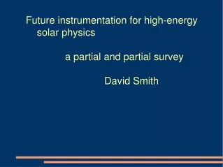
Future Instrumentation for Solar and Stellar Research at Radio Wavelengths T. S. Bastian NRAO
Ground Based Radio Initiatives: the Next 10 yrs • EVLA – Expanded Very Large Array • ALMA – Atacama LargeMillimeter Array • CARMA – Combined Array for Research in Millimeter Astronomy • FASR – Frequency Agile Solar Radiotelescope • ATA – Allen Telescope Array, formerly the 1HT. • LOFAR - aLOwFrequency ARray
And Beyond … • SKA – Square Kilometer Array
How do Radio Telescopes Image the Sky? High resolution imaging radio telescopes exploit Fourier synthesis techniques. The basic element is not a single antenna, but a pair of antennas: an interferometer. The signals from a pair of antennas are multiplied and integrated – correlated- after compensating for the difference in geometrical path length. The output from the correlator is a single Fourier component of the radio brightness distribution on the sky. If the distance between two antennas – the baseline – is L, then the angular scale to which the interferometer is sensitive is approximately q = l/L.
By deploying N antennas over a two dimensional area, one can measure N(N-1)/2 Fourier components of the 2D radio brightness I instantaneously on a large number of angular scales and orientations. An inverse Fourier transform of the measured Fourier components yields I*B, the convolution of I with the instrumental response function B. Deconvolution techniques are used to recover I. The sensitivity of a radio telescope depends on the collecting area, the sensitivity of the receivers, and the signal bandwidth, and the integration time. The imaging fidelity depends upon how well the Fourier transform of the sky is sampled, how well sources of systematic error are eliminated, and how well deconvolution algorithms perform.
The EVLA The EVLA (Phase 1) Phase 1: Frequency coverage: The EVLA will be able to operate at any frequency between 1-50 GHz. Up to four independently tunable pairs of frequencies in a given band. Sensitivity: Continuum sensitivity to improve by factors of a few (n<10 GHz) to more than a factor of 20 (n=10-50 GHz) Spectral line capabilities: A new correlator will provide many more frequency channels (at least 16384), process up to 8 GHz bandwidth in each pol’n channel, and provide much higher spectral resolution (as high as 1 Hz!). Phase 2: The primary goal of the second phase will be to increase the angular resolution of the VLA by a factor of 10. This will be done by incorporating the inner VLBA antennas and adding 8 new antennas: The New Mexico Array. In addition, low frequency systems will be installed at the prime focus and a new ultracompact array configuration will be added (E configuration).
The EVLA The EVLA (Phase 1) VLA Phase 1 Phase 2
ALMA ALMA is currently a project of the NRAO and ESO. It is possible that the NOAJ/Japan will join as an equal partner.
Nested rings with diameters of 150 m, 420 m, 1.1 km, 3 km, and 14 km provide resolutions from 1.4” to 15 mas at 1 mm. Configurations
ALMA Science • Formation of galaxies and clusters • Formation of stars • Formation of planets • Creation of the elements • Old stellar atmospheres • Supernova ejecta • Low temperature thermal science • Planetary composition and weather • Structure of Interstellar gas and dust • Astrochemistry and the origins of life
ALMA Timeline • Design and Development Phase Jun 1998 - Oct 2001 • International partnership established 1999 • Prototype antenna contracts Feb 2000 • Delivered to VLA site 4Q2001 • Prototype interferometer 2Q 2002 • Construction Oct 2001-2010 • Production antenna contract 1Q 2003 • Production antenna at Chajnantor 2Q 2004 • Interim operations late 2005 • Full operations 2010
CARMA Combine the six 10.4 m antennas at OVRO with the nine 6.1 m BIMA antennas . 772 m2 collecting area (~0.1 ALMA) Frequency coverage: 115 GHz 230 GHz 345 GHz (planned) 4 configurations with up to 0.1” resolution OVRO BIMA
CARMA will be the best mm-l array for a period of several years. After completion of ALMA, it will continue to provide access to the northern sky. The current timeline calls for site construction and moving the OVRO antennas in 2003. The BIMA array will be moved in 2004. The array will become operational in 2005. CARMA science will concentrate on detecting, identifying, and mapping emission from organic molecules in a variety of contexts (e.g., comets), protostellar and protoplanetary disks, star formation, emission from molecular gas and dust at high z, and the cosmic microwave background.
What is FASR? The Frequency Agile Solar Radiotelescope is a solar-dedicated instrument designed to perform broadband imaging spectroscopy. It will be designed to support temporal, spatial, and frequency resolutions well-matched to problems in solar physics. FASR involves NJIT, NRAO, UMd, Berkeley SSL, and Lucent
FASR Science • Nature & Evolution of Coronal Magnetic Fields Measurement of coronal magnetic fields Temporal & spatial evolution of fields Role of electric currents in corona • Coronal Mass Ejections Birth Acceleration B, nrl, nth Prominence eruptions • Flares Energy release Plasma heating Electron acceleration and transport
Region showing strong shear: radio images show high B and very high temperatures in this region from Lee et al (1998)
FASR Science • Nature & Evolution of Coronal Magnetic Fields Measurement of coronal magnetic fields Temporal & spatial evolution of fields Role of electric currents in corona • Coronal Mass Ejections Birth Acceleration B, nrl, nth Prominence eruptions • Flares Energy release Plasma heating Electron acceleration and transport
20 April 1992 C3 C3 C2 C2 10:04:51 UT 10:31:20 UT 10:45:22 UT SOHO/LASCO 11:49:14 UT
Noise storm Bastian et al. (2001)
FASR Science • Nature & Evolution of Coronal Magnetic Fields Measurement of coronal magnetic fields Temporal & spatial evolution of fields Role of electric currents in corona • Coronal Mass Ejections Birth Acceleration B, nrl, nth Prominence eruptions • Flares Energy release Plasma heating Electron acceleration and transport As a comprehensive, dedicated solar instrument sensitive to magnetic fields, eruptive phenomena, their locations, and physical properties, FASR is an excellent instrument for LWS/space weather programs.
FASR Science (cont) • The “thermal” solar atmosphere Coronal heating - nanoflares Thermodynamic structure of chromosphere in AR, QS, CH Formation & structure of filaments/prominences • What about night time observing?? See S. White
Status and Plans The NAS/NRC Astronomy and Astrophysics Survey Committee has recommended an integrated suite of three ground and space based instruments designed to meet the challenges in solar physics in the coming decade. These are: Advanced Technology Solar Telescope (O/IR) Frequency Agile Solar Radiotelescope (radio) Solar Dynamics Observatory (O/UV/EUV) FASR is currently under review by the NAS/NRC Solar and Space Science Survey Committee.
Plans • 2002-2003 Technical study (NSF/ATI) • 2003-2004 Design, develop, prototype susbsystems • 2005-2006 Construction • 2006 Operations commence
The ATA The ATA is a project of the SETI organization. It is being largely funded by Paul Allen (co-founder of Microsoft) although Nathan Myhrvold (former Chief Technology Officer to Microsoft) has also contributed. The primary purpose of the ATA is to do SETI work. Unlike the other instruments discussed today, its main function will not be as an imaging instrument. Rather, it will be a beam forming instrument. The ATA will use 350 x 6.1 m antennas to form a pencil beam. The beam will be placed on a target and sophisticated DSP techniques will be used to search for signals over a frequency range of 0.5-11.5 GHz.
Offset Gregorian Antenna 6.1 m x 7.0 m Primary Az-El Drive Log-periodic Feed Shroud (feed can’t see ground or array) 2.4 m Secondary
LOFAR is a concept for an imaging array operating between 10 – 240 MHz with arcsec resolution. It is being pursued by the NRL, NFRA, & MIT/Haystack. • High Redshift Universe • unbiased sky surveys, select highest z galaxies • trace galactic & intergalactic B fields • Epoch of Reionization: search for global signature, detect and map spatial structure • Cosmic Ray Electrons and Galactic Nonthermal Emission • map 3D distribution, test expected origin and acceleration in SNRs • Bursting and Transient Universe • broad-band, all-sky monitoring for variable/transient sources • search for coherent emission sources; e.g. from stars, quasars, & extra-solar planets • Solar-Terrestrial Relationships • study fine-scale ionospheric structures • image Earth-directed CMEs (as radar receiver)
SM146 Concept(VLA Scientific Memorandum #146) • Perley & Erickson concept • Standalone stations along VLA arms • VLA arm easement enough room for 100 m stations • Logistical issues remain – how will the cows like them? • Might proceed with EVLA-I • Augmented SM146 • Addition of A+ capability • Might proceed with EVLA-II
High Sensitivity StationPrototype for LOFAR Low Frequency Antennas Analogous to one VLA antenna but with >10X the sensitivity ~100 meter diameter @74MHz: VLA antenna ~ 125 m2 LWA Station 1500 m2
SM146 CAPABILITY SM146 SM146 SM146
Relationship to LOFAR • SM146 is largely independent of LOFAR • LOFAR is much more complex than SM146 • It has a substantial technology development element as well as purely scientific goals • Larger Freq. Range (LOFAR: 10-240 MHz; SM146: 10-90 MHz)) • Many more stations (>100) • Complex configuration (log spiral) • MUCH more software, etc … • SM146 and LOFAR: parallel, mutually beneficial • SM146 development clearly meshes with LOFAR technical developments for low frequencies (< 100 MHz) • Might SM146 develop into the low frequency portion of LOFAR?
SKA Finally, it is worth mentioning SKA. No one knows what exactly it will be, what it will do, where it will be, or how we’ll do it, but it’s generally agreed that it’s the next big thing. And we know it’s real, because it has a web site (several, in fact). The SKA project is presently an international consortium. The US partner is itself a consortium of UC Berkeley SETI Inst. MIT/Haystack Cornell/NAIC NRAO Caltech/JPL Harvard SAO Univ Minnesota Ohio State Univ Georgia Tech
Originally conceived as a “red shift machine” operating at 1.4 GHz and below, the basic idea behind SKA is to push to extremely high sensitivity. For spectral line work, an increase in bandwidth is not an option. And receiver technology is now approaching quantum limits. The solution, therefore, is to exploit an extremely large collecting area: one square kilometer. To put that in perspective, that’s 100 VLAs! The community – both national and international – is behind the basic concept. But the detailed specifications and how to build it at reasonable cost have not been determined. Several concepts are being considered. A few are: Large-N arrays (US) Large-f-ratio mirrors with derigibles (Canada) Many Arecibos (China) Adaptive reflectors (NFRA)