Download
1 / 34
340 likes | 352 Views
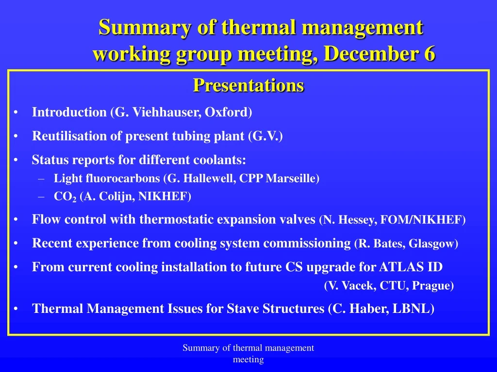
Summary of thermal management working group meeting, December 6. Presentations Introduction (G. Viehhauser, Oxford) Reutilisation of present tubing plant (G.V.) Status reports for different coolants: Light fluorocarbons (G. Hallewell, CPP Marseille) CO 2 (A. Colijn, NIKHEF)

E N D
Summary of thermal management working group meeting, December 6 Presentations • Introduction (G. Viehhauser, Oxford) • Reutilisation of present tubing plant (G.V.) • Status reports for different coolants: • Light fluorocarbons (G. Hallewell, CPP Marseille) • CO2 (A. Colijn, NIKHEF) • Flow control with thermostatic expansion valves (N. Hessey, FOM/NIKHEF) • Recent experience from cooling system commissioning (R. Bates, Glasgow) • From current cooling installation to future CS upgrade for ATLAS ID (V. Vacek, CTU, Prague) • Thermal Management Issues for Stave Structures (C. Haber, LBNL) Summary of thermal management meeting
MEANS COOLANTS Summary of thermal management meeting
Issues: • Try to use as much of the existing pipework as possible • (mainly the tubing through the magnet to the ID volume) • External components on access platforms and in USA15 • can be considered less static: • Much hinges on delivery and evaporation pressure of final • coolant, impedance to evacuate vapour, • critical temperature of chosen fluid Summary of thermal management meeting
Operating temperature of silicon detectors Can we estimate a Si operation temperature for sufficient safety margin @ L>>1034? From Nobu Unno’s September 6th talk: -30°C on SCT Sensors, requiring (my guess) ~-45°C evaporation in on-detector cooling channels 15°C (Si – coolant) DT Reasonable? Conservative?... Summary of thermal management meeting
Power dissipation of silicon detectorelectronics No estimate given (anywhere in this conference) of dissipation of electronics (Given the much higher activity within the electronics + reduced radius (1/r2) of new B layer, extra track / background activity at luminosities ~ 1035 Summary of thermal management meeting
The fluids…Two (maybe 3) candidate fluids: C2F6, CO2 & (maybe still) C3F8 A few pros and cons: C2F6: Enthalpy ~ 100J/g, Pevap~ 4 bara @ -45°C, Tcrit ~ 20°C Liquid delivery pressure in warm zones ≥ 30 bar CO2:Enthalpy ~ 280J/g Pevap ~ 7 bara @ -45°C, Tcrit ~ 30°C Higher evaporation pressure higher HTC Triple point temperature ~ -56°C (dry ice formation) Liquid delivery pressure in warm zones ≥ 70 bar C3F8: Enthalpy~100J/g, Pevap < 1 bara*@ -45°C, Tcrit ~ 60°C * low evaporation pressure needs special treatment Summary of thermal management meeting
Déverseur/ Back-pressure regulator for groups of circuits (Individual Pevap) Performance squeezed here! ATLAS SCT & Pixels: Principle of present C3F8 system Liquid h.p. Vapour h.p. Vapour l.p. Liquid l.p. Summary of thermal management meeting
Attention: Tcrit ~20°C Possible cycle with C2F6 rgh liquid return to pit Detent Surface condenser Compressor Pin~4.5bara, Pout~15bar ΔH ~ 110 J/g Evaporation @ -45°C: Atten Summary of thermal management meeting
CO2 properties: p-H diagram Attention: Tcrit ~30°C Attention: Pdeliv ~ 60bar P = 60bar liquid Pressure [bar] ΔH(-35C) = 280 kJ/kg P = 12 bar 2-phase gas Summary of thermal management meeting Enthalpy [kJ/kg]
Cooling circuits have little margin for reducing Si temperature. Also compressor cooling less efficient: (reduced flow of cooling gas) expect a reduced MTBF? Problems with the present C3F8 system (Which might require ‘external’ intervention) Back-pressure regulators contribute substantial (& variable) insertion loss (CV variability) being mastered…; (2) Significant insertion loss in deeply embedded hex’s, heaters; (1) & (2) low compressor aspiration pressure (~1barabs) (3) Very high compression ratio (~x17) across compressors due to the very high choice of condenser pressure; (1), (2) & (3) conspire to put the compressor in a regime of reduced throughput (pumping speed) and hotter operation Summary of thermal management meeting
Off-detector layout, inc DCS Det. environmental DCS Detector DCS HEX DCS Heaters DCS Summary of thermal management meeting
Toward a simplified circulator with reduced compressor stress (and enhanced compressor M.T.B.F.) Condensers operating With lower input pressure than in USA15 location ATLAS Surface Buildings Example: rgDh(vapour) ~ 200mbar(C3F8) Example: rgDh(liquid) ~ 14bar(C3F8) Tubing to be sized for dynamic DP Remote Control Pressure regulators Pin ~ 14bar (flow proportional to heat load) USA15 ATLAS pit (d ~ 92m) Compressors Tracker Summary of thermal management meeting
There is yet space! Summary of thermal management meeting
A ‘graded external fix’ approach to problems with the present C3F8 system (Integrable steps in the cooling system for the tracker upgrade) APPROACH (1) Eliminate back-pressure regulators + use compressor aspiration tank pressures (by varying compressor speed using motor speed controller) to control evaporation pressure in pixel and SCT circuits Moduarity issues? Summary of thermal management meeting
A ‘graded external fix’ approach to problems with the present C3F8 system IF APPROACH (1) DOES NOT SUFFICIENTLY INCREASE Si DETECTOR OPERATING TEMPERATURE MARGIN… APPROACH (2) Install ‘local’ (COLD ~-50°C) condensers (service platforms) Condenser cooled either using LN2 /GN2from liquid argon calorimeter cooling loops or a compressor system (R404A?) How to circulate C3F8 primary coolant back to capillaries?: (2-i) Using liquid pumps (hydraulic or pneumatic drive for B field) (2-ii) Using 2nd (external) evaporator & existing Haug Compressors in USA15 Summary of thermal management meeting
A ‘graded external fix’ approach to problems with the present C3F8 system IF APPROACH (1) DOES NOT SUFFICIENTLY INCREASE Si DETECTOR OPERATING TEMPERATURE MARGIN… APPROACH (2) Install ‘local’ (COLD ~-50°C) condensers (service platforms) Condenser cooled either using LN2 /GN2from liquid argon calorimeter cooling loops or a compressor system (R404A?) How to circulate C3F8 primary coolant back to capillaries?: (2-i) Using liquid pumps (hydraulic or pneumatic drive for B field) (2-ii) Using 2nd (external) evaporator & existing Haug Compressors in USA15 Summary of thermal management meeting
2.i Enhancing Si operating temperature margin of the present C3F8 evaporative cooling system Low temperature condenser operating on GN2 (LN2 boiloff) or else R404a, ex C3F8 compressor system (Condenser at highest point on ATLAS platforms) Remote control pressure regulators Pin ~ 14-17bar Priming height (maximum possible) rDh(liquid)10m ~1.5bar(C3F8) (boosts pump output) Tracker * Use Haug compressors to cool local condensers in UX (no longer in primary cooling loop) Liquid pump (possibly 2-stage): Hydraulic/pneumatic drive for high B-field operation Must generate ~14-17 bar C3F8 capillary input pressure USA15 Haug compressors in USA15 Summary of thermal management meeting
Principle of modified P-H cycle : recovery of present C3F8 system Pressure regulators & present choice of capillary (Ø,L) DP liquid via (2-stage?) pump Evaporation @-45°C DP (DT) between Evaporation & Condensation determined by sizing of exisiting internal services Condensation Summary of thermal management meeting
Fluorocarbons can be mixed (blended ) to arrive at compromise thermodynamic properties (many modern refrigerants are blends) • This was tested with C3F8/C4F10 (2 papers in Fluid Phase Equilibria 2000-2001) Mixture thermodynamic, transfer properties calculated & set up as ‘temporary’ folders in NIST database verified by measurement (sound velocity in superheated phase) Summary of thermal management meeting
CO2 Status report A. Colijn, NIKHEF • CO2: Why? • CO2: Cooling system for LHCb vertex detector • CO2: Research plans at NIKHEF Summary of thermal management meeting
CO2 properties: p-H diagram Attention: Tcrit ~30°C liquid Pressure [bar] ΔH(-35C) = 280 kJ/kg P = 12 bar 2-phase gas Summary of thermal management meeting Enthalpy [kJ/kg]
LHC-b ‘VELO’ vertex tracker CO2 cooling system: (NIKHEF) Cooling plant area VELO area detectors Fully assembled under testing Under construction Installed now Summary of thermal management meeting
VTCS cooling cycle Summary of thermal management meeting
LHCb: Mechanical construction Automatic valves Accumulator BACK Heat exchanger CO2 pumps FRONT Summary of thermal management meeting
NIKHEF & CO2: Cooling plant Compact CO2 cooling plant Test setup Primary CO2 cooler Secondary CO2 circulation circuit Compressor (with oil) Accumulator Condensor condensor Detector Heat exchanger Pump Summary of thermal management meeting
USA15: C3F8 compressors Back-pressure regulator rack: setting of evaporation pressure (temperature) (64 / 324 circuits) Summary of thermal management meeting
Infrastructure at CPPM Summary of thermal management meeting
GUI in PVSS II Finite state machine in PVSS to send fluid through pixel ladder by sequencing pneumatic valves Summary of thermal management meeting
GUI in PVSS II Part of a run of 1000 heat/cool cycles (Accelerated Thermal Stress Test of thermal interfaces in a pixel stave) Machine a état finie pour envoyer fluide vers l’échelle séquencing des vannes pneumatiques Summary of thermal management meeting
New compressor at CPPM : capacity = 4kW Aspiration buffer PID controllers Condensor Summary of thermal management meeting