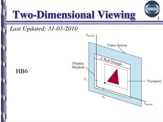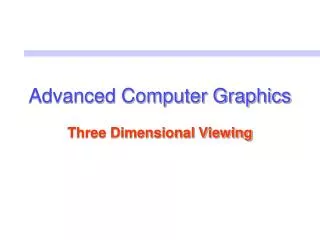
Three-Dimensional Viewing
Three-Dimensional Viewing. CVGLab. Introduction. We want to create and control a camera that produces perspective projections. We also need ways to take more control of the camera’s position and orientation. We also need to achieve precise control over the camera’s view volume.

Three-Dimensional Viewing
E N D
Presentation Transcript
Three-Dimensional Viewing CVGLab
Introduction • We want to create and control a camera that produces perspective projections. • We also need ways to take more control of the camera’s position and orientation. • We also need to achieve precise control over the camera’s view volume. • We also describe how clipping is done against the camera’s view volume.
The Camera Revisited View Volume – a portion of a rectangular pyramid, whose apex is at the eye. -. View angle θ : given in degrees and sets the angel between the top and bottom walls of the pyramid. -. Aspect ratio : any window parallel to the xy-plane
The Camera Revisited • Setting the View Volume -. The shape of the camera’s view volume is encode in the projection matrix that appears in the graphic pipeline. N – the distance from the eye to the near plane F – the distance from the eye to the far plane
The Camera Revisited • Positioning and Pointing the Camera -. The General Camera with Arbitrary Orientation and Position -. A camera can have any position in a scene and any orientation. -. The coordinate system has its origin a the eye and has three axes u, v and n. -. The axes are pointed in directions given by the vectors u, v and n. n : the negative n-axis, in the direction –n u : to the right of v : upward
The Camera Revisited -. Pitch : an air plane is the angle that its longitudinal axis make with the horizontal. (running from tail to nose and having direction –n) -. Rolls : rotating about its longitudinal axis. (the amount of rotation relative to the horizontal) -. Heading : direction in which it is headed.
The Camera Revisited • What gluLookAt ( ) Does: Some Mathematical underpinnings n : parallel to the vector eye – look n = eye – look u : off to the side u, v : perpendicular to n up : “upward” direction To summarize, given eye, look, and up, we form n = eye – look. u = up n, v = n u
The Camera Revisited -. The modelview matrix is the product of two matrices : the matrix V, the matrix M -. The following matrix does the trick : here, (dx, dy, dz) = (-eye.u, -eye.v, -eye.n) Extended point eye to homogeneous coordinates
Building a Camera in a Program • Sliding the Camera -. Means : to move it along one of its own axes – that is, in the u, v, or n direction – without rotating it. function : slide (delU, delV, delN) • Rotating the Camera -. roll, pitch or yaw the camera : each of these involves a rotation of the camera about one of its own axes. -. To roll the camera is to rotate it about its own n-axis. u´ = cos(α)u + sin(α)v; v´ = -sin(α)u + cos(α)v;
Perspective Projections of 3D Objects -. When a vertex emerges from this matrix, it is in eye coordinates – that is, in the coordinate system of the eye. • Perspective Projection of a point -. The fundamental operation in a perspective projection is projecting a 3D to a 2D point on a plane.
Perspective Projections of 3D Objects -. X* is in the same ratio to Px as the distance N is to the distance |Pz| Since Pz is negative x* = NPx / (-Pz) y* = NPy / (-Pz)
Perspective Projections of 3D Objects • Perspective Projection of a Line • Projecting Parallel Lines point A = (Ax, Ay, Az) vector c = (cx, cy, cz) -. the parametric form : p(t) = A + c(t) -. The parametric form for the projection of this line : -. suppose the line A + ct is parallel to the viewplane then, cx = 0 -. Cz < 0, t increases, -. All parallel lines share the same vanishing point. The receding edges, are not parallel to the viewplane and hence converge onto a vanishing point.
Perspective Projections of 3D Objects • Lines that pass behind the Eye
Perspective Projections of 3D Objects • The Anomaly Viewing Long Parallel Lines
Perspective Projections of 3D Objects • Incorporating Perspective into the Graphics Pipeline • Adding Pseudodepth -. Using the previous expression for Mpersp, all points would have the same depth, z* = -N. But we need to preserve the depth of each point so that we can do hidden surface removal. -. Let z* be linear in Pz and have the same denominator as x*and y*.
Perspective Projections of 3D Objects -. Choose the pseudodepth to vary between -1 and 1. -. Let z* = -1 on the near plane, where Pz = -N. Let z* = 1 on the far plane, where Pz = -F.
Perspective Projections of 3D Objects • Using Homogeneous Coordinates -. To convert a point from ordinary coordinates to homogeneous coordinates, append a 1; -. To convert a point from homogeneous to ordinary coordinates, divide all of the components by the last component, and discard the fourth component. -. A point P in homogeneous representation by such a matrix M to from MP=Q the final component of Q will always be unaltered : It is still w. Therefore, we can convert the Q back to ordinary coordinates in the usual fashion.
Perspective Projections of 3D Objects -. Something new happens if we deviate from a fourth row of (0, 0, 0, 1) -. To find out, we divide through by the fourth component and discard it. The result is -. Carries a 3D point P into another 3D point P`
Perspective Projections of 3D Objects -. Ignoring the third component is equivalent to replacing it by zero, as in -. (perspective projection) = (perspective transformation) + (orthographic projection) • The Geometric Nature of the Perspective Transformation -. The perspective transformation alters the 3D point P into another 3D point according, in order to “prepare” the point for projection. -. The perspective transformation “warps” objects so that, when viewed with an orthographic, they appear the same as the original objects do when viewed with a perspective projection.
Perspective Projections of 3D Objects • Details of the Transformed View Volume; Mapping into the Canonical View Volume -. Opengl composes the perspective transformation with another mapping that scales and shifts this parallelepiped into the canonical view volume, a cube that extends from –1 to 1 in each dimension. . The bottom plane transforms to the y = bott plane; . The left plane transformations to the x = left plane; . The right plane transformations to the x = right plane.
Perspective Projections of 3D Objects -. Performs perspective transformation plus a scaling and a shear to transform the camera’s view volume into the canonical view volume (the projection matrix)
Perspective Projections of 3D Objects • Clipping Faces against the View Volume Each point is clipped against the cannonical viewing volume. -.A face edge can be represented as A + (C-A)t for vertices A and C of the face edge. -. Check both vertices to see if they lie inside or outside the cannonical viewing volume. -. Perform clipping if any edge is outside the cannonical viewing volume.