Download
1 / 24
280 likes | 525 Views
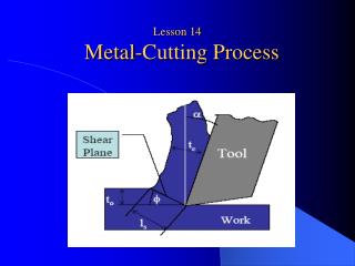
Lesson 14 Metal-Cutting Process. Extensively adv. 广阔地, 广泛 circumscribe 围绕;限制 确定 … 的范围; circumscribed circle 外接圆 scrap n. 残余物, 废料.

E N D
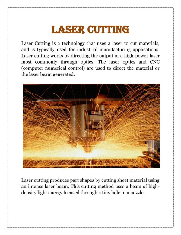
Extensively adv.广阔地, 广泛 circumscribe 围绕;限制 确定…的范围; circumscribed circle 外接圆 scrap n. 残余物, 废料 Metal-cutting processes are extensively used in the manufacturing industry. They are characterized by the fact that the size of the original workpiece is sufficiently large that the final geometry can be circumscribed by it, and that the unwanted material is removed as chips, particles, and so on. The chips are a necessary means to obtain the desired tolerances, and surfaces. The amount of scrap may vary from a few percent to 70% - 80% of the volume of the original work material.
anticipated 预先的 预期的scarcity n. 缺乏, 不足 die n. 钢型, 硬模, 冲模 die casting 压铸 Owing to the rather poor material utilization of the metal-cutting processes, the anticipatedscarcity of materials and energy, and increasing costs, the development in the last decade has been directed toward an increasing application of metal-forming processes. However, die costs and the capital cost of machines remain rather high; consequently, metal-cutting processes are, in many cases, the most economical, in spite of the high material waste, which only has value as scrap.
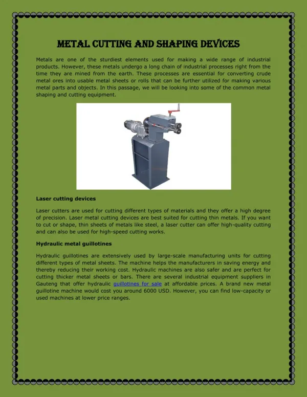
Diecasting Raw output with running system from die casting. Running system may so strong that mechanical trimming method is required The picture shows a mold base with circular mold insert. The product produced will the negative form of the mold insert
Therefore, it must be expected that the material removal processes will for the next few years maintain their important position in manufacturing. Furthermore, the development of automated production systems has progressed more rapidly for metal-cutting processes than for metal-forming processes.
Imprint vt. 印; 盖印于 在...上压出记号 使带上..的特征 铭刻; 牢记 In metal-cutting processes, the imprinting of information is carried out by a rigid medium of transfer (the tool), which is moved relative to the workpiece, and the mechanical energy is supplied through the tool. The final geometry is thus determinedfrom the geometryof the tool and the patternof motions of the tool and the workpiece. The basic process is mechanical: actually, a shearing action combined with fracture.
Cutting speed 200m/min 300m/min Feed rate 0.10mm/rev 0.025mm/rev
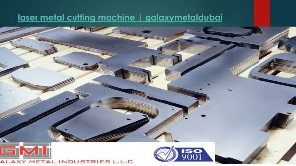
reaming 铰孔 Reamer n. 钻孔器, 刀, 铰床 Shaping n. adj. 刨削 成形(的) planing 龙门刨 Honing n. 珩磨, 搪磨 Lapping n. 研磨, 磨合, 精研, 抛光 As mentioned previously, the unwanted material in metal-cutting processes is removed by a rigid cutting tool, so that the desired geometry, tolerances, and surface finish are obtained. Examples of processes in this group are turning, drilling, reaming, milling, shaping, planing, broaching, grinding, honing, and lapping.
surface creation 表面成型法 Most of the cutting or machining processes are based on a two-dimensional surface creation, which means that two relative motions are necessary between the cutting tool and the work material. These motions are defined as the primary motion, which mainly determines the cutting speed, and the feed motion, which provides the cutting zone with new material
In turning the primary motion is provided by the rotation of the workpiece, and in planing it is provided by the translation of the table; in turning the feed motion is a continuous translation of the tool, and in planing it is an intermittent translation of the tool. Translation n. [物][数]平移 intermittent adj. 间歇的, 断断续续的
Cutting Speed The cutting speed v is the instantaneous velocity of the primary motion of the tool relative to the workpiece (at a selected point on the cutting edge). The cutting speed for turning, drilling, and milling processes can be expressed as v = d n m/min ( 14.1 ) where v is the cutting speed in m/min, d the diameter of the workpiecc to be cut in meters, and n the workpiece or spindle rotation in rev/min. Thus v, d, and n may relate to the work material or the tool, depending on the specific kinematic pattern. In grinding the cutting speed is normally measured in m/s.
Feed The feed motion f is provided to the tool or the workpiece and, when added to the primary motion, leads to a repeated or continuous chip removal and the creation of the desired machined surface. The motion may proceed by steps or continuously. The feed speed vf is defined as the instantaneous velocity of the feedmotion relative to the workpiece (at a selected point on the cutting edge).
For turning and drilling, the feed f is measured per revolution (mm/rev) of the workpiece or the tool; for planing and shaping f is measured per stroke (mm/stroke) of the tool or the workpiece. In milling the feed is measured per tooth of the cutter fz(mm/tooth); that is, fzis the displacement of the workpiece between the cutting action of two successive teeth. The feed speed vf(mm/min) of the table is therefore the product of the number of teeth z of the cutter, the revolutions per minute of the cutter n, and the feed per tooth (vf = nzfz ).
A plane containing the directions of the primary motion and the feed motion is defined as the working plane, since it contains the motions responsible for the cutting action.
Depth of Cut (Engagement) In turning the depth of cut a (sometimes also called back engagement) is the distance that the cutting edge engages or projects below the original surface of the workpiece. The depth of cut determines the final dimensions of the workpiece. In turning, with an axial feed, the depth of cut is a direct measure of the decrease in radius of the workpiece and with radial feed the depth of cut is equal to the decrease in the length of workpiece.
In drilling, the depth of cut is equal to the diameter of the drill. For milling, the depth of cut is defined as the working engagement ae and is the radial engagement of the cutter. The axial engagement (back engagement) of the cutter is called ap.
undeformed 无形变的 deform v. (使)变形 Chip Thickness The chip thickness h1 in the undeformed state is the thickness of the chip measured perpendicular to the cutting edge and in a plane perpendicular to the direction of cutting. The chip thickness after cutting (i. e., the actual chip thickness h2) is larger than the undeformed chip thickness, which means that the cutting ratio or chip thickness ratio r = h1/h2is always less than unity.
Chip Width The chip width b in the undeformed state is the width of the chip measured along the cutting edge in a plane perpendicular to the direction of cutting.
Area of Cut For single-point tool operations, the area of cut A is the product of the undeformed chip thickness h1 and the chip width b (i.e. , A = h1 b). The area of cut can also be expressed by the feed f and the depth of cut aas follows: h1 = f sinκ and b = a/sinκ(14.2) Where κis the major cutting edge angle ( i. e., the angle that the cutting edge forms with the working plane) . Consequently, the area of cut is given by A = f a(14.3)
Comparison of Shapers and Planers Although both the planer and the shaper are able to machine flat surfaces, there is little overlapping in their application. They differ greatly in construction and in the method of operation. The planer is especially adapted to large work: the shaper can do only small work. On the planer the work is moved against a stationary tool: on the shaper the tool moves across the work, which is stationary. On the planer the tool is fed into the work; on the shaper the work is usually fed across the tool. The drive on the planer table is either by gears or by hydraulic means. The shaper ram also can be driven in this manner, but many times a quick-return link mechanism is used. Most planers differ from shapers in that they approach more constant-velocity cutting speeds. Tools used in shaper and planer work are single point as used on a lathe, but are heavier in construction. The holder is designed to secure the tool bit near the centerline of the holder or the pivot point rather than at an angle as is customary with lathe toolholders. Cutting tools for the planer operation are usually tipped with high-speed steel, cast alloy, or carbide inserts. High-speed steel or cast alloys are commonly used in heavy roughing cuts and carbides for secondary roughing and finishing. Cutting angles for tools depend on the tool used and the workpiece material. They are similar to angles used on other single-point tools, but the endclearance does not exceed 4 degrees. Cutting speeds are affected by the rigidity of the machine, how the work is held, tool, material, and the number of tools in operation. Worktables on planers and shapers areconstructed with T-slots to hold and clamp parts that are to be machined
Power requirements and bale characteristics for a fixed and a variable chamber baler A variable-chamber baler (VCB) and a fixed-chamber baler (FCB) were compared with respect to power requirements, field capacity, and bale mass. The fixed-chamber baler was operated with and without a coarse cutting mechanism (FCB/C and FCB, respectively). Average PTO power requirements were similar (10 to 15 kW) but peak power requirements were considerably greater with the FCB (38 kW) and the FCB/C (42 kW) than with the VCB (15 kW). The VCB had a material flow of 4.1 tonne of dry matter (DM) per hour (t/h) compared to 4.8 and 4.6 t/h with the FCB and FCB/C respectively. Bale dry matter mass was not affected by baler type nor by cutting and averaged 263 kg for a standard 1.22 m wide by 1.22 m diameter bale. Bale dry matter density varied, however, between 152 and 192 kg/m3 because of variations in material flow and moisture. Forage chopped with the FCB/C had an average length of cut of 150 mm. Keywords: forage, round bales, power, mass, density, chop length