Download
1 / 21
210 likes | 432 Views
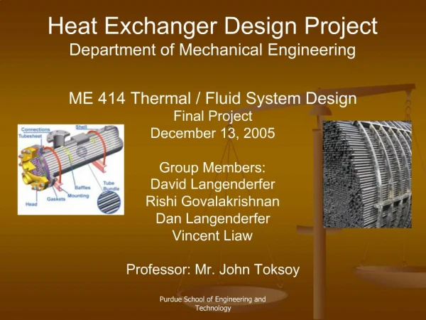
Thermal Control Design J.D. Huang ( 黃正德 ) Mechanical Engineering Section National Space Program Office April 14, 2005. Contents. Key Requirements Thermal Information Geometric Mathematical Model Assumptions Thermal Analysis Cases Thermal Analysis Results Conclusions.

E N D
Thermal Control Design J.D. Huang (黃正德) Mechanical Engineering Section National Space Program Office April 14, 2005
Contents • Key Requirements • Thermal Information • Geometric Mathematical Model • Assumptions • Thermal Analysis Cases • Thermal Analysis Results • Conclusions
Key TCS Requirements • Passive thermal control • The thermal control should be achieved through passive elements, as thermal blankets, insulation, and surface finishes. • Materials should be selected for low-outgassing characteristics. • Thermal margin • For components that have no thermal control or have passive control only, an uncertainty margin of 5. • Heaters • If thermostats are used, the thermostat shall be redundant. • Each heater shall be provided with a ground-commandable override capability. • Each heater shall be sized to control to 5 deg C above its minimum allowable temperature or to control the component at its minimum allowable temperature with 25% excess control authority.
Thermal Information - Attitude • Altitude : 400 ~ 800 km • Beta angle : -90 ~+90 deg • Attitude : Normal mode, Safehold mode, Orbit Control mode
Thermal Information- Temperature Limits • Payload Operating (°C) Non-operating (°C) • GPS Occ. Rx : -20 to +60 -30 to +70 • GPS Occ. Ant. -125 to +105 -125 to +105 • TBB -10 to +50 -20 to +70 • TBB Ant. -125 to +105 -125 to +105 • TIP -10 to +50 -10 to +50 • SSR/PC -10 to +40 -25 to +40 • BUS • Power • Battery -5 to +30 -5 to +30 • BCR+PDU -25 to +50 -35 to +60 • Solar Array -100 to +105 -100 to +105 • C&DH • SBFC -20 to +65 -45 to +70 • IIU -20 to +65 -45 to +70 • Mass Memory -20 to +65 -45 to +70
Thermal information-Temperature Limits (Continued) ADCS Operating (°C) Non-operating (°C) Torque Rods -30 to +40 -50 to +61 Reaction Wheel -10 to +50 -35 to +61 Sun Sensor -95 to +80 -105 to +90 Earth Sensors -40 to +40 -40 to +61 IRU (3-axis) -25 to +55 -25 to +55 Magnetometer -60 to +50 -60 to +50 GPS Rx. -10 to +40 -25 to +40 GPS Ant. -55 to +71 -55 to +71 TT&C Hybrid -10 to +40 -25 to +40 Diplexer -10 to +40 -25 to +40 Transceiver -10 to +40 -25 to +40
Thermal information-Temperature Limits (Continued) Propulsion Operating (°C) Non-operating (°C) Latching Valve +7 to +55 +7 to +55 Press. Transducer +7 to +55 +7 to +55 Thruster +7 to +55 +7 to +55 Tank +7 to +55 +7 to +55 Filter +7 to +55 +7 to +55 Fill Drain Valve +7 to +55 +7 to +55
Geometric Mathematical Model • Internal model MLI Radiator L-Band S-Band RW SSR/PC TBB C&DH ADCS GPS RX Torque Rod PDU Tank TIP LACH VALVE Battery BCR GPS Occ. x x y y z z
Geometric Mathematical Model (Continued) • External model • Orientation (Normal Mode) Eclipse Earth Earth Orientation Sun • Orientation (Safe-hold Mode) Rotation Rate=2 rev./orbit Eclipse Earth Sun Orientation Sun
Assumptions • +Y and –Y side solar panels will be deployed to 90 deg from the stowed condition and decoupled from the spacecraft bus. • Thermal capacitance of each component is assumed to be 900 (J/kg°C) x mass (kg). • Contact conductance of battery is assumed to be 200 (W/m2°C) and Others are 30 (W/m2°C). • RCS tank is isolated ( 0.01 W/°C ) from deck and covered with MLI to reduce the internal radiation coupling with other components. • Heat conductions between deck and the side panels are through eighteen(18) M4 screws with the value of conductance of 0.76 (W/m2°C).
Thermal Analysis Results-Temperature Prediction • The worst hot and cold temperatures for Normal Operating.
Thermal Analysis Results-Temperature Prediction (Cont’) • The worst hot and cold temperatures for Safe-hold Mode.
Thermal Analysis Results-Temperature Plots • Normal Hot, H=400 km, =0o • Normal Hot, H=800 km, =0o Daytime Daytime Daytime Eclipse Daytime Eclipse
Thermal Analysis Results-Temperature Plots (Continued) • Normal Hot, H=400 km, =90o • Normal Hot, H=800 km, =90o (10 Orbits) (10 Orbits) (10 Orbits)
Thermal Analysis Results-Temperature Plots (Continued) • Normal Cold, H=800 km, =0o • Normal Cold, H=800 km, =90o (10 Orbits)
Thermal Analysis Results-Temperature Plots (Continued) • Safe-hold Mode, H=800 km, =0o • Safe-hold Mode, H=800 km, =61o (10 Orbits) (10 Orbits)
Conclusions • For both normal operating and safe-hold modes, all worst hot and cold predicted temperatures are within the operating/non-operating temperature ranges with proper margins. • The total required radiator areas on the side panels are 0.42 m2. • The total maximum required heater powers are 11.74 W for the normal operating mode and 18.1 W for safe-hold mode. • The predicted radiator areas and heater powers can be reduced if less power consumption is required. • All the thermal analysis results will be updated again if further design information is given.