Download

1 / 63
630 likes | 750 Views
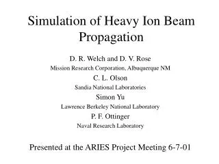
The ISTTOK Heavy Ion Beam Diagnostic. HIBD concept. Multiple cell detector (Secondary ions). Primary beam detector. Toroidal direction. HIBP concept. ISTTOK magnetic configuration. x. z. Plan view. Toroidal field inside the coil aperture =. ISTTOK magnetic configuration.

E N D
HIBD concept Multiple cell detector (Secondary ions) Primary beam detector Toroidal direction
ISTTOK magnetic configuration x z Plan view Toroidal field inside the coil aperture =
ISTTOK magnetic configuration Position coils field xc Side section Toroidal field outside the coil aperture (x) =
Plasma current magnetic field For radial profiles Asymmetric current profiles are generated by a combination of symmetric profiles
Beam trajectories i x,y,z In numerical simulation equations uses constant B and E; B and E are updated on each iteration cycle (toroidal curvature negleted); Electric field are modelled freely (core and edge) – normally an inverted parabola with peak eV ~ 3/2 KTe
Cs+ 20 keV coils plasma Cs++
Detector arrangement Cross section front view
Beam attenuation MOST IMPORTANT IONIZATION REACTIONS:
Density and temperature profiles Primary beam attenuation Secondary beam generation (dl is the projection of detector cell height into the primary beam path) Secondary beam attenuation (to integrate along secondary beam path dl’)
Plasma source (Cs+) Child-Langmuir perveance condition in ISTTOK HIBD
Determination of Beam attenuation Simplified
Simplified version A1=0 (week primary beam attenuation due to tertiary ion production) B=1 (weak secondary beam attenuation) The generation factor is related to the secondary currents by: The current at the detector cell j is obtained by integration over the element dl obtained by the projection from the detector cell height length into the primary beam path.
Detector currents per row (linha) Detector rows
ne(0) = 11019 Te(0) = 200 eV Eb=22 keV I0=1 uA The beam attenuation in ISTTOK induces only first order effects to consider on the computation of the profile of
Including the effect of attenuation on the secondary beams A1=0 (week primary beam attenuation due to tertiary ion production) B≠1 (moderate secondary beam attenuation (ISTTOK)) The difference between injected primary beam current and detected primary beam current is equal to ½ of the all secondary beam current generated along the primary beam The total secondaries current lost by ionization to terciaries is given by the difference between the initial secondaries currents generated by the primary beam and the secondaries currents detected at the detector
Determination of the corrent lost by a single secondaries’ beam For ISTTOK Expanding the exponencial and taking only linear terms becomes:
So, one could find the fraction of each secondary beam current lost to terciary ionization by the ratio to the total lost current of all secondaries’ beams:
Calculations show that: Primary beam and secondary beams have similar radial trajectories in the plasma Effective cross sections have similar shapes for I+I2+ and I2+I3+ Therefore have similar shape to Confirmed by calculations for several ISTTOK plasma temperature and density profiles
Replacing integrals by discret sums Experimentaly determined
Absolute value of secondaries current at the ionization volume on the primary beam The recovery of the absolute value of the generation factor is now more acurate The remaining difference is due to ionization from primary to tertiary ions Correction: see following slides
Generation of tertiaries from the primary beam (on the same volumes of generation of secondaries) And the tertiaries generation factor can be given by
Using the aproximation Experimentaly determined And obtain the tertiary currents at te ionization volume using: unknown
Estimation of the total current of the tertiaries: For a given temperature the ratio between production of secondaries and tertiaries is constant (only depends on the cross sections’ ratio) In the plasma the temperature varies along the radius, but sensivity of the currents’ ratio to temperature profile changes is low (Current ratio of terciaries to secondaries)
Excellent recovery of absolute values of a) Te = 100 eV e ne = 51018 m-3, b) Te = 200 eV e ne = 11019 m-3 e c) Te = 300 eV e ne = 1.51019 m-3.
Example of effect of negleting atenuation factors Detected currents A1=0 B=1 Using full version of algorithm A1=0 B≠1 A1 ≠0 B≠1
Determination of electron density and electron temperature Ratio between detected currents from 2 different ionization processes on the same volume Table of effective cross sections
In ISTTOK two ion species are used Hg+Hg3+ and Xe+Xe2+ (E = 22 keV, Hg = 32.0º, Xe = 33.3º).
The two beams have overlaped trajectories Detector currents
The Hg2+ currents are not detected, they can be estimated from the Xe2+ currents using the average of the ionization ratio between the limits of temperature of ISTTOK (quasi constant function with temperature) Therefore the generation of Hg2+ can now be estimated from And the Hg+ primary beam current at each ionization point given by
Plasma potential measurements using the primary beam Distinguishing 2 ns delay resolution (/)TOF ~310-4 for =7.2 s of time-of-flight of the beam pulse from modulator to detector. ()TOF = TOF(t2) - TOF(t1) = ½(v0)-1{e{(ltr,t2) - (ltr,t1)}/E0}dltr + add Accounts for shifts on trajectories due to external and internal magnetic field changes
Plasma potential measuremenst using the secondaries Absolute plasma potential measurements Average plasma potential measurements Energy conservation K1F + eVF = K1P + eVP K2P + 2eVP = K2D + 2eVD VP = (K2D - K1F) + (2VD - VF)
TOF-path module Control module “Start” “Stop” MCAD 620 mm Ch1 Ch2 Ch3 Ch4 Cylindrical plates XY-alignment plates Z-plates y x z
Plasma Poloidal Field Measurements Important: In ISTTOK all ion trajectories are very close to radial
Poloidal magnetic field outside the plasma: Secondary ions average acceleration from ionization point to plasma perifery Velocity of primary beam at ionization point X secondary time of flight Secondary beam position at cell (1) secondary beam increment from plasma bondary to detector position Primary beam initial position
Recursive calculation allows to determine the accelerations at ionization point poloidal field module can be obtained from