Download

1 / 7
70 likes | 156 Views
Detailed follow-up on chicane shielding enhancements for precise energy deposition study with segmented coils and diverse shielding materials. Simulation using ROOT-based geometry for better accuracy and visual representation.

E N D
Chicane shielding and energy deposition (IPAC’13 follow-up) Pavel Snopok IDS-NF phone meeting June 4, 2013
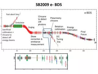
Updates to the chicane • Yellow: coils, subdivided into smaller segments (3 longitudinal, 2 radial, 12 azimuthal) for more precise energy deposition study. Radius = 43-53 cm, length of 18 cm, on-axis field 1.5 T throughout the channel. • Cyan: W shielding (pure W, need to change the density to 60%), 4 cm thickness @ 32-36 cm radii. • Gray around cyan: inner and outer SS pipe, 2 cm thick each @ 30-32 & 36-38 cm radii to enclose W, yet stay 5 cm clear of the coils. • Magenta: proton absorber, 10 cm of Be, outer radius = 30 cm. • Z=0 corresponds to 30 m downstream of the target.
ROOT-based geometry • For irradiation study the chicane is simulated in MARS15. Field maps for MARS simulations are generated by G4beamline. • Complicated geometry of the chicane, => adding shielding is not possible using only MARS extended geometry. • ROOT-based geometry framework for MARS is used with a wide variety of basic volumes provided by the ROOT TGeo module. • The volume of each shielding or coil segment can be calculated precisely in ROOT; removes the uncertainty intrinsic to MARS Monte-Carlo based volume calculation. • Easy to visualize your geometry for debugging (3D visual above is produced by ROOT). • Geometry is straightforward to read/comprehend/modify as needed • Most important for seamless shielding is the TGeoCtub elementary volume (cut tubes with arbitrary entrance/exit angles).
(Vertical) beam size considerations No shielding, coil inner R = 43 cm, muon flux (main) is not affected With shielding starting at R = 30 cm, muon flux is clearly affected No coils, smaller statistics, test that R = 43 cm is indeed a “safe” radius Beam pipe + shielding shape + coil radii toward the center of the chicane need further modifications.
Reference case: no shielding • Average deposited power density (DPD) per coil is shown • The limit of 0.15 mW/g is exceeded in a number of coils; however, it could be reduced to within the limits by providing extra shielding in about half of the coils. • DPD peaks at 15.8 mW/g, that translates into 42.6 kW/m for Cu coils or 33.3 kW/m for SC coils.
First attempt @ shielding, 4 cm of W Max average DPD = 1.7 mW/g Max DPD per segment = 9.1 mW/g • Average deposited power density in the coils is at maximum 1.7 mW/g. • On average: the limit of 0.15 mW/g is exceeded in a smaller number of coils, only those between 32 and 36 m downstream of the target. • Need to change W density to 60%. • At the same time, certain coil segments can get up to 9.1 mW/g (3 longitudinal, 2 radial, 12 azimuthal segments per coil) due to the non-uniformity of energy deposition.
Summary • ROOT-based geometry allows to simulate the complex shape of the chicane + shielding. • Current simulations are based on pure W, should be redone with 60% density (which increases the amount of material considerably, hence, the radius of the coils as well). • Coil and shielding shape need modifications compatible with the beam width at the center of the chicane. • Average DPD with 4 cm of W drops almost an order in magnitude: 15.8 => 1.7 mW/g, although still an order of magnitude larger than the required 0.15 mW/g (even worse if a conservative limit of 0.1 mW/g is used as suggested by Kirk McDonald). • As expected, segmentation of the coils reveals that energy deposition is not uniform, max = 9.1 mW/g. • I would like to continue energy deposition studies, but I will need some help from the Targetry group with their expertise.