Week 1 Introduction and Data Link Layer
Week 1 Introduction and Data Link Layer. Layers. OSI reference model Each layer communicates with its peer layer through the use of a protocol The communication between n and n-1 is known as an interface. Transmission. Reception. Layers. Physical Layer

Week 1 Introduction and Data Link Layer
E N D
Presentation Transcript
Layers • OSI reference model • Each layer communicates with its peer layer through the use of a protocol • The communication between n and n-1 is known as an interface Week 1
Transmission Week 1
Reception Week 1
Layers • Physical Layer • The physical later is concerned with transmitting raw bits over a communication channel. • The design issues have to do with making sure that when one side sends a 1 bit, it is received by the other side as a 1 bit, not as a 0 bit. • Typical questions here ar e how many volts should be used to represent a 1 and how many for a 0, how many microseconds a bit lasts, whether transmission may proceed simultaneously in both directions, how the initial connection is established and how it is torn down when both sides are finished, and how many pins the network connector has and what each pin is used for. • The design issues here deal largely with mechanical, electrical, and procedural interfaces, and the physical transmission medium, which lies below the physical layer. Physical layer design can properly be considered to be within the domain of the electrical engineer. • Examples: RS232C, X.25, Ethernet Week 1
Layers • Data Link Layer • Sometimes called the link layer transmits chunks of information across a link. • It deals with problems as checksumming to detect data corruption; coordinating the use of shared media as in LAN (Local Area Network); and addressing (when multiple systems are reachable as in a LAN) • It is common for different links to implement different data link layers and for a node to support several data link layer protocols, one for each of the types of links to which the node is attached. • Example: HDLC, SDLC, X.25, Ethernet, ATM. Week 1
Layers • Network Layer • The network layer enables any pair of systems to communicate with each other. • A fully connected network is one in which every pair of nodes has a direct link between its nodes, but this kind of topology does not scale beyond a few nodes • Network layer must find a path through a series of connected nodes and nodes along the path should forward packets in the appropriate direction. • The network layer deals with problems such as route calculation, packet assembly and reassembly (when different links on the path have different maximum packet sizes), and congestion control. • Examples: IP, IPX, ATM. Week 1
Layers • Transport Layer • This layer provides a reliable communications stream between a pair of systems • It deals with errors that can be introduced by the network layer, such as lost packets, duplicated packets, packet reordering, and fragmentation and reassembly • It is also nice if the transport layer reacts to congestion in the network • Example: TCP Week 1
Layers • Session Layer • The session layer assumes that a reliable virtual point-to-point connection has been made and contains specs for the dialog between the two end systems such as dialog discipline, data grouping, and recovery of an interrupted session. Specs are also included for initiating and concluding a session. Many network specs contain little or no session specs and leave these decisions to the applications. • Presentation Layer • Provides transformation of data to standardize the application interface. Also provides some network services such as encryption, compression, and text re-formatting. • Application Layer • This layer plays the same role as the 'application interface' in operating systems. Provides network services to users (applications) of the network in a distributed processing environment: examples transaction server, file transfer protocol, network management, electronic mail, and terminal access to remote applications. Week 1
PDUs and SDUs Application Application APDU PSDU Presentation Presentation PPDU SSDU Session Session TSDU SPDU Transport Transport NSDU TPDU Network Network NPDU LSDU Data Link Data Link LPDU PhSDU Physical Physical PhPDU Week 1
Service Models • Layer n-1 can provide either a connectionless service or connection-oriented service • Communication consists of three phases in a CO-service • Connection setup • Data transfer • Connnection release • Associated with each of these phases are two functions: • Layer n initiates the function • Layer n-1 informs layer n that some layer n process in some other node is requesting a connection Week 1
Service Models • Services can vary in their degree of reliability • Datagram service (also known as best-effort) accepts data but makes no guarantees as to delivery in that data may be lost, duplicated, delivered out of order, or mangled. • A reliable service guarantees the data will be delivered in the order transmitted, without corrupting, duplication or loss. Week 1
Examples • In the TCP/IP protocol suite, network layer is connectionless, TCP offers reliable connection-oriented service, UDPs datagram service • ATM offers a connection-oriented, unreliable service that can be viewed as a network layer. For IP over ATM, ATM is viewed by IP as a a data link layer • It’s good to know about layering but it should not be taken that seriously; however it is a good learning and communication tool. Week 1
application: supporting network applications ftp, smtp, http transport: host-host data transfer tcp, udp network: routing of datagrams from source to destination ip, routing protocols link: data transfer between neighboring network elements ppp, ethernet physical: bits “on the wire” application transport network link physical Internet protocol stack Week 1
Application Application Presentation TCP IP Stack Session OSI Reference Model Transport Transport TCP, UDP Internet Network Data Link Link Physical TCP/IP Stack Week 1
Each layer: Distributed “entities” implement layer functions at each node entities perform actions, exchange messages with peers network link physical application transport network link physical application transport network link physical application transport network link physical application transport network link physical Layering: logical communication Week 1
E.g.: transport take data from app add addressing, reliability check info to form “datagram” send datagram to peer wait for peer to ack receipt network link physical application transport network link physical application transport network link physical application transport network link physical application transport network link physical data data data ack Layering: logical communication transport transport Week 1
M M H H H H H H H H H H H H t t t n l n l t n t n t M M M M application transport network link physical application transport network link physical M M Protocol layering and data Each layer takes data from above • adds header information to create new data unit • passes new data unit to layer below source destination message segment datagram frame Week 1
roughly hierarchical national/international backbone providers (NBPs) e.g. BBN/GTE, Sprint, AT&T, IBM, UUNet interconnect (peer) with each other privately, or at public Network Access Point (NAPs) regional ISPs connect into NBPs local ISP, company connect into regional ISPs local ISP local ISP NAP NAP Internet structure: network of networks regional ISP NBP B NBP A regional ISP Week 1
Tiered Networks • A Tier 1 Network is an IP network which connects to the entire Internet solely via Settlement Free Interconnection, commonly known as peering. • Tier 1 - A network that peers with every other network to reach the Internet. • Tier 2 - A network that peers with some networks, but still purchases IP transit to reach at least some portion of the Internet. • Tier 3 - A network that solely purchases transit from other networks to reach the Internet. Week 1
Routing • In commercial network routing between autonomous systems, hot-potato routing is the practice of passing traffic off to another AS as quickly as possible, thus using their network for wide-area transit. • Cold-potato routing is the opposite, where the originating AS holds onto the packet until it is as near to the destination as possible. Week 1
Global Backbone Provider Week 1
Important Properties of a Network • Scope - A network architecture should solve as general a problem as possible • Scalability - Would work well with very large networks and be also efficient with small networks • Robustness: The network should continue to operate even if nodes or links fail • Safety barriers: A fault does not spread beyond a safety barrier, for example a router confines a broadcast storm to a single LAN • Self-stabilization: After a failure, the network will return to normal operation without human intervention within a reasonable time, e.g., routing protocols • Fault detection • Autoconfigurability • Tweakability • Migration Week 1
How • A new network "philosophy and architecture," is replacing the vision of an Intelligent Network. The vision is one in which the public communications network would be engineered for "always-on" use, not intermittence and scarcity. It would be engineered for intelligence at the end-user's device, not in the network. • And the network would be engineered simply to "Deliver the Bits" not for fancy network routing Fundamentally, it would be a Stupid Network. • In the Stupid Network, the data would tell the network where it needs to go. (In contrast, in a circuit network, the network tells the data where to go.) In a Stupid Network, the data on it would be the boss. Week 1
Scope of this Course • We will study how a packet finds its way from a source to a destination • Role of Layer 2 • Ethernet, PPP, 802.11 • Role of Layer 3 • IP Addressing • Routing • OSPF, BGP • Internet architecture • We will also study emerging trends in IP networks • IP QoS • MPLS (Multiprotocol Label Switching) • Traffic Engineering • Multimedia networking Week 1
Our goals: understand principles behind data link layer services: error detection, correction sharing a broadcast channel: multiple access link layer addressing reliable data transfer, flow control: instantiation and implementation of various link layer technologies The Data Link Layer Week 1
5.1 Introduction and services 5.2 Error detection and correction 5.3Multiple access protocols 5.4 Link-Layer Addressing 5.5 Ethernet 5.6 Hubs and switches 5.7 PPP 5.8 Link Virtualization: ATM and MPLS Link Layer Week 1
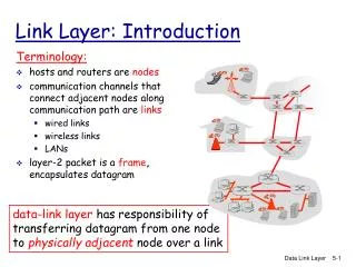
Some terminology: hosts and routers are nodes communication channels that connect adjacent nodes along communication path are links wired links wireless links LANs layer-2 packet is a frame,encapsulates datagram “link” Link Layer: Introduction data-link layer has responsibility of transferring datagram from one node to adjacent node over a link Week 1
Datagram transferred by different link protocols over different links: e.g., Ethernet on first link, frame relay on intermediate links, 802.11 on last link Each link protocol provides different services e.g., may or may not provide reliable data transfer over link transportation analogy trip from Princeton to Lausanne limo: Princeton to JFK plane: JFK to Geneva train: Geneva to Lausanne tourist = datagram transport segment = communication link transportation mode = link layer protocol travel agent = routing algorithm Link layer: context Week 1
Link Layer Services • Framing, link access: • encapsulate datagram into frame, adding header, trailer • channel access if shared medium • “MAC” addresses used in frame headers to identify source, dest • different from IP address! • Reliable delivery between adjacent nodes • seldom used on low bit error link (fiber, some twisted pair) • wireless links: high error rates • Q: why both link-level and end-end reliability? Week 1
Link Layer Services (more) • Flow Control: • pacing between adjacent sending and receiving nodes • Error Detection: • errors caused by signal attenuation, noise. • receiver detects presence of errors: • signals sender for retransmission or drops frame • Error Correction: • receiver identifies and corrects bit error(s) without resorting to retransmission • Half-duplex and full-duplex • with half duplex, nodes at both ends of link can transmit, but not at same time Week 1
link layer implemented in “adaptor” (aka NIC) Ethernet card, PCMCI card, 802.11 card sending side: encapsulates datagram in a frame adds error checking bits, rdt, flow control, etc. receiving side looks for errors, rdt, flow control, etc extracts datagram, passes to rcving node adapter is semi-autonomous link & physical layers frame frame Adaptors Communicating datagram rcving node link layer protocol sending node adapter adapter Week 1
5.1 Introduction and services 5.2 Error detection and correction 5.3Multiple access protocols 5.4 Link-Layer Addressing 5.5 Ethernet 5.6 Hubs and switches 5.7 PPP 5.8 Link Virtualization: ATM Link Layer Week 1
Error Detection • EDC= Error Detection and Correction bits (redundancy) • D = Data protected by error checking, may include header fields • Error detection not 100% reliable! • protocol may miss some errors, but rarely • larger EDC field yields better detection and correction Week 1
Parity Checking Two Dimensional Bit Parity: Detect and correct single bit errors Single Bit Parity: Detect single bit errors 0 0 Week 1
Checksumming: Cyclic Redundancy Check • view data bits, D, as a binary number • choose r+1 bit pattern (generator), G • goal: choose r CRC bits, R, such that • <D,R> exactly divisible by G (modulo 2) • receiver knows G, divides <D,R> by G. If non-zero remainder: error detected! • can detect all burst errors less than r+1 bits • widely used in practice (ATM, HDCL) Week 1
CRC Example Want: D.2r XOR R = nG equivalently: D.2r = nG XOR R equivalently: if we divide D.2r by G, want remainder R D.2r G R = remainder[ ] Week 1
5.1 Introduction and services 5.2 Error detection and correction 5.3Multiple access protocols 5.4 Link-Layer Addressing 5.5 Ethernet 5.6 Hubs and switches 5.7 PPP 5.8 Link Virtualization: ATM Link Layer Week 1
Multiple Access Links and Protocols Two types of “links”: • point-to-point • PPP for dial-up access • point-to-point link between Ethernet switch and host • broadcast (shared wire or medium) • traditional Ethernet • upstream HFC • 802.11 wireless LAN Week 1
Multiple Access protocols • single shared broadcast channel • two or more simultaneous transmissions by nodes: interference • collision if node receives two or more signals at the same time multiple access protocol • distributed algorithm that determines how nodes share channel, i.e., determine when node can transmit • communication about channel sharing must use channel itself! • no out-of-band channel for coordination Week 1
Ideal Mulitple Access Protocol Broadcast channel of rate R bps 1. When one node wants to transmit, it can send at rate R. 2. When M nodes want to transmit, each can send at average rate R/M 3. Fully decentralized: • no special node to coordinate transmissions • no synchronization of clocks, slots 4. Simple Week 1
MAC Protocols: a taxonomy Three broad classes: • Channel Partitioning • divide channel into smaller “pieces” (time slots, frequency, code) • allocate piece to node for exclusive use • Random Access • channel not divided, allow collisions • “recover” from collisions • “Taking turns” • Nodes take turns, but nodes with more to send can take longer turns Week 1
Channel Partitioning MAC protocols: TDMA TDMA: time division multiple access • access to channel in "rounds" • each station gets fixed length slot (length = pkt trans time) in each round • unused slots go idle • example: 6-station LAN, 1,3,4 have pkt, slots 2,5,6 idle • TDM (Time Division Multiplexing): channel divided into N time slots, one per user; inefficient with low duty cycle users and at light load. • FDM (Frequency Division Multiplexing): frequency subdivided. Week 1
Channel Partitioning MAC protocols: FDMA FDMA: frequency division multiple access • channel spectrum divided into frequency bands • each station assigned fixed frequency band • unused transmission time in frequency bands go idle • example: 6-station LAN, 1,3,4 have pkt, frequency bands 2,5,6 idle • TDM (Time Division Multiplexing): channel divided into N time slots, one per user; inefficient with low duty cycle users and at light load. • FDM (Frequency Division Multiplexing): frequency subdivided. time frequency bands Week 1
Random Access Protocols • When node has packet to send • transmit at full channel data rate R. • no a priori coordination among nodes • two or more transmitting nodes ➜ “collision”, • random access MAC protocol specifies: • how to detect collisions • how to recover from collisions (e.g., via delayed retransmissions) • Examples of random access MAC protocols: • slotted ALOHA • ALOHA • CSMA, CSMA/CD, CSMA/CA Week 1
Assumptions all frames same size time is divided into equal size slots, time to transmit 1 frame nodes start to transmit frames only at beginning of slots nodes are synchronized if 2 or more nodes transmit in slot, all nodes detect collision Operation when node obtains fresh frame, it transmits in next slot no collision, node can send new frame in next slot if collision, node retransmits frame in each subsequent slot with prob. p until success Slotted ALOHA Week 1
Pros single active node can continuously transmit at full rate of channel highly decentralized: only slots in nodes need to be in sync simple Cons collisions, wasting slots idle slots nodes may be able to detect collision in less than time to transmit packet clock synchronization Slotted ALOHA Week 1
Suppose N nodes with many frames to send, each transmits in slot with probability p prob that node 1 has success in a slot = p(1-p)N-1 prob that any node has a success = Np(1-p)N-1 For max efficiency with N nodes, find p* that maximizes Np(1-p)N-1 For many nodes, take limit of Np*(1-p*)N-1 as N goes to infinity, gives 1/e = .37 Slotted Aloha efficiency Efficiency is the long-run fraction of successful slots when there are many nodes, each with many frames to send At best: channel used for useful transmissions 37% of time! Week 1
CSMA (Carrier Sense Multiple Access) CSMA: listen before transmit: If channel sensed idle: transmit entire frame • If channel sensed busy, defer transmission • Human analogy: don’t interrupt others! Week 1
CSMA collisions spatial layout of nodes collisions can still occur: propagation delay means two nodes may not hear each other’s transmission collision: entire packet transmission time wasted note: role of distance & propagation delay in determining collision probability Week 1