Download
1 / 59
710 likes | 1.7k Views
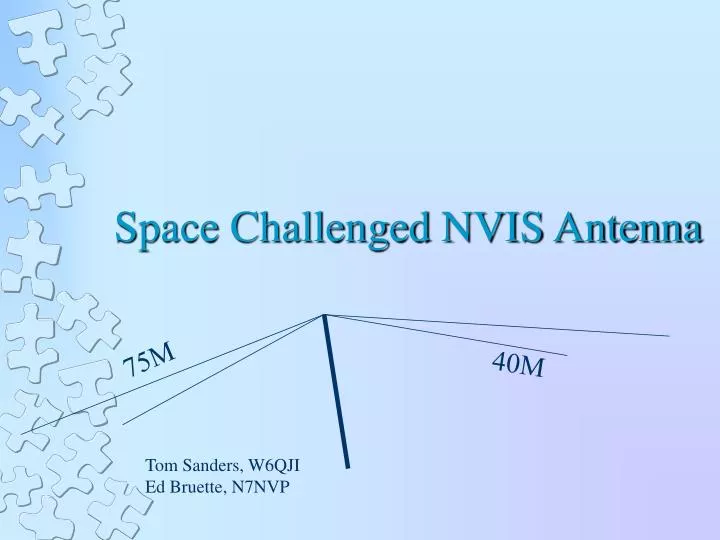
75M. 40M. Space Challenged NVIS Antenna. Tom Sanders, W6QJI Ed Bruette, N7NVP. Near Vertical Incident Skywave. Cloud Warmer. What is NVIS?. Propagation Theory. Propagation Theory. NVIS Effect. 300 Mile Coverage. Propagation Considerations. “D” layer losses

E N D
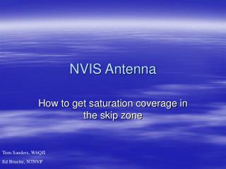
75M 40M Space Challenged NVIS Antenna Tom Sanders, W6QJI Ed Bruette, N7NVP
Near Vertical Incident Skywave Cloud Warmer What is NVIS?
Propagation Considerations • “D” layer losses • Ionospheric scattering for vertical propagation • Importance of critical frequency
75Meters 40 Meters Left side of dual band
Computer Simulation EZNEC Ver. 4.0 High Accuracy Mode
Wire layout Fence line Feed point Fence line Fence line
Top down view Fence line Feed point
75 Meter SWR 4.0
Bandwidth 75 Meters • 4050 – 2:1 • 3960 – dip • 3860 – 2:1
Bandwidth 40 Meters • 7190 – 2:1 • 7250 – dip • 7370 – 2:1
How It Went Together • Materials • Construction • Modifications
Parts List • 1 Center insulator • 1 1.5” PVC Slip coupler • 2 or 3 Hose clamps • 14 ga. Insulated wire • 1 10’ TV mast • 1 5’ TV mast • Tie wraps as desired • 1 Fence stake • Coax to the shack W6QJI
End of 75M wires are 6’ above ground End of 40M wires are 4’ above ground
Element Lengths • 75 Mtr legs = 57 ft • 40 Mtr legs = 39 ft • Prune these lengths to meet your ground conditions
Beamwidth • 75 Mtrs 41 deg. To 139 deg. • 40 Mtrs 39 deg. To 141 deg.
Hints & tips • Solder wires at the feed point • Solder feed point pigtail to all other wires • Coax should be perpendicular to the antenna
Hints & tips (cont.) • Ground conditions will drive element lengths • Wet vs.. dry • Use an antenna analyzer!!! • Tune 75M first, then 40M • Minimize the catenaries in the wires but not too tight – the wire will stretch • Maintain the spacing between the 75 & 40M elements
Can 60M be Incorporated in This Antenna? • Of course!
60 Meter elements 48’ 48’ 15’ 6’ 6’ It’s as Easy as Adding 2 Elements!
Not Enough Real Estate for a Dual Band? Try this!
32.25’ 32.25’ 4.5’ 15’ 4.5’ 40M wire Tunable on 75M