Download
1 / 1
10 likes | 219 Views
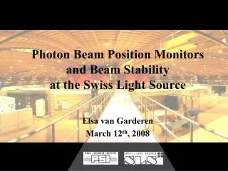
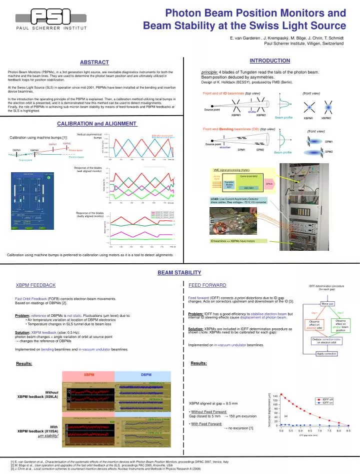
ABSTRACT Photon Beam Monitors (PBPMs), in a 3rd generation light source, are inevitable diagnostics instruments for both the machine and the beam lines. They are used to determine the photon beam position and are ultimately utilized in feedback loops for position stabilization.

E N D
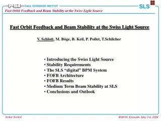
ABSTRACT Photon Beam Monitors (PBPMs), in a 3rd generation light source, are inevitable diagnostics instruments for both the machine and the beam lines. They are used to determine the photon beam position and are ultimately utilized in feedback loops for position stabilization. At the Swiss Light Source (SLS) in operation since mid-2001, PBPMs have been installed at the bending and insertion device beamlines. In the introduction the operating principle of the PBPM is explained. Then, a calibration method utilizing local bumps in the electron orbit is presented, and it is demonstrated how this method can be used to detect misalignments. Finally, the role of PBPMs in achieving sub-micron beam stability by means of feed-forwards and PBPM feedbacks at the SLS is highlighted. INTRODUCTION principle:4 blades of Tungsten read the tails of the photon beam. Beamposition deduced by asymmetries. Design of K. Holldack (BESSY), produced by FMB (Berlin). Photon Beam Position Monitors and Beam Stability at the Swiss Light Source CALIBRATION and ALIGNMENT Vertical asymmetrical bumps BPM after source point Calibration using machine bumps [1]: BPM before source point XBPM2 XBPM1 vert. bump (μm) DBPM1 Photon beam DBPM2 Electron beam time (s) Source point Response of the blades (well aligned monitor) VME signal processing (Hytec). Analog signal Carrier board 8002 2 BPM before source point Transition Module 8201 3 EPICS blade signal (V) ADC 8401 1 4 LCAD: Low Current Asymmetry Detector triaxe cables; Bias voltage= -70 V; I/U converter time (s) Response of the blades (badly aligned monitor) 2 3 blade signal (V) 3.5 cm 1 4 ID beamlines => XBPMs have motors time (s) E. van Garderen , J. Krempaský, M. Böge, J. Chrin, T. Schmidt Paul Scherrer Institute, Villigen, Switzerland Calibration using machine bumps is preferred to calibration using motors as it is a tool to detect alignments. BEAM STABILITY XBPM FEEDBACK FEED FORWARD IDFF determination procedure (for each gap) • Fast Orbit Feedback (FOFB) corrects electron beam movements. • Based on readings of DBPMs [2]. • Problem:reference of DBPMs is not static. Fluctuations (μm level) due to: • Air temperature variation at location of DBPM electronics • Temperature changes in SLS tunnel due to beam loss • Solution:XBPM feedback (slow: 0.5 Hz): • photon beam changes = angle variation of orbit at source point → changes the reference of DBPMs • Implemented on bending beamlines and in-vacuum undulator beamlines. Feed forward (IDFF) corrects a priori distortions due to ID gap changes.Acts on correctors upstream and downstream of the ID [3]. Problem: IDFF has a good efficiency to stabilise electron beam but internal ID steering effects cause displacement of photon beam. Solution:XBPMs are included in IDFF determination procedure as shown (note: XBPMs need to be calibrated for each gap): Implemented on in-vacuum undulator beamlines. Move gap Step 2 Step 1 Observe effect on photon beam position Observe effect on electron orbit Deduce correction kicks on electron orbit Apply correction Results: Results: XBPM DBPM DBPM before ID preliminary calibration x Without XBPM feedback (X09LA) 5 μm y 30 μm DBPM after ID • XBPM aligned at gap = 8.5 mm • Without Feed Forward: • Gap closed to 5 mm → 150 μm excursion • With Feed Forward: • → no excursion [1] x y DBPM before ID With XBPM feedback (X10SA) μm stability! DBPM after ID U19 gap size (mm) [1] E. van Garderen et al., Characterisation of the systematic effects of the insertion devices with Photon Beam Position Monitors, proceedings DIPAC 2007, Venice, Italy [2] M. Böge et al., User operation and upgrades of the fast orbit feedback at the SLS, proceedings PAC 2005, Knoxville, USA [3] J. Chrin at al., Local correction schemes to counteract insertion devices effects, Nuclear Instruments and Methods in Physics Research A (2008)