Imaging without lenses
90 likes | 260 Views
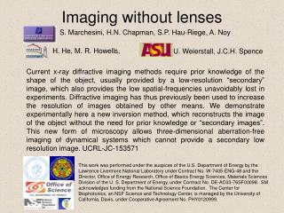
Imaging without lenses. S. Marchesini, H.N. Chapman, S.P. Hau-Riege, A. Noy. H. He, M. R. Howells,. U. Weierstall, J.C.H. Spence.

Imaging without lenses
E N D
Presentation Transcript
Imaging without lenses S. Marchesini, H.N. Chapman, S.P. Hau-Riege, A. Noy H. He, M. R. Howells, U. Weierstall, J.C.H. Spence Current x-ray diffractive imaging methods require prior knowledge of the shape of the object, usually provided by a low-resolution “secondary” image, which also provides the low spatial-frequencies unavoidably lost in experiments. Diffractive imaging has thus previously been used to increase the resolution of images obtained by other means. We demonstrate experimentally here a new inversion method, which reconstructs the image of the object without the need for prior knowledge or “secondary images”. This new form of microscopy allows three-dimensional aberration-free imaging of dynamical systems which cannot provide a secondary low resolution image. UCRL-JC-153571 This work was performed under the auspices of the U.S. Department of Energy by the Lawrence Livermore National Laboratory under Contract No. W-7405-ENG-48 and the Director, Office of Energy Research, Office of Basics Energy Sciences, Materials Sciences Division of the U. S. Department of Energy, under Contract No. DE-AC03-76SF00098. SM acknowledges funding from the National Science Foundation. The Center for Biophotonics, an NSF Science and Technology Center, is managed by the University of California, Davis, under Cooperative Agreement No. PHY0120999.
Long WD External Optical Microsocope Phosphor Mirror 1 Sample Gold balls on SiN. Removable Photodiode 1, Absorption filter. Mirror 2 and PT 2 Undulator Beam stops 105 mm 80 mm. 25 mm Zone plate monchromator Energy dispersion slit . 25 microns Field limiting aperture. 5 microns Experiment Layout of the diffraction chamber used for this experiment at BL 9.0.1 at Advanced Light Source, LBL Sample Sample: 50 nm gold balls randomly distributed on SiN window (~100nm thickness and 22 m2) =2.1nm (588 eV) Detector: 1024 1024 Princeton back-illuminated CCD Au 50nm SiN 100nm Si substrate Side view of sample
Every 20 iterations new support Amplitude constraint Hybrid Input Output Phase retrieval with blind support known, j unknown s support estimated from Patterson function b=0.9 feedback s=2 gaussian width (pixels) t=0.2 threshold Every 20 iterations we convolve the reconstructed image (the absolute value of the reconstructed wavefield) with a Gaussian to find the new support mask. The mask is then obtained by applying a threshold at 20% of its maximum. Missing low frequency components are treated as free parameters.
image reconstruction with shrink-wrapping support Measured x-ray diffraction pattern 1 20 100 1000 Object support constraint Object SEM x-ray Iterative reconstruction techniques require a known shape (support) of the object. Previous work has obtained that by x-ray microscopy. We reconstruct the support and the object simultaneously. No prior knowledge is needed. The reconstruction gives a better estimate of the support. The better support gives a better reconstruction. This will enable single-molecule diffraction and high-resolution imaging of dynamic systems. 300 nm
Clusters of gold spheres 3D single cluster 5-7 clusters 8 clusters This particular 3D cluster was chosen to have a small number of balls for visualization purposes - the algorithm also works with a much larger number of balls. Single clusters 2-4 clusters These simulations show that the algorithm works not only for two-clusters objects
Gray-scale images and complex objects bugs with different histograms Rec. image Rec. Supp. Orig. image Histogram Without beamstop With beamstop Number of electrons for a given density The greyscale image demonstrates that the algorithm does not depend on any “atomicity” constraint provided by the gold balls. The complex object is of particular interest since it is well known that the reconstruction of complex objects is much more difficult than real objects, but is possible using either disjoint, precisely known or specially shaped supports. The use of focused illumination will allow users to select either one or two-part objects (which may be complex) from a field. Original object Complex probe Amplitude after probe Comparison of the reconstructed, support and original object amplitudes the real part is shown, blue is negative, red/yellow is positive. (each ball is multiplied by a constant phase)
1 1 adjusting support 1 Support 1 Support 2 HiO error 0.5 Support 3 Support 4 Rfact 0.5 1-xcorr 0.5 0 0 2 4 6 8 10 12 14 16 0 0 2 4 6 8 10 12 14 16 0 0 2 4 6 8 10 12 14 16 Shrink-wrap vs HIO Original object Even for low noise, HIO can achieve a reasonable reconstruction only if the support mask is set to the boundary known at essentially the same resolution to which we are reconstructing the object. σ indicates the size in pixels of the gaussian used to obtain the low resolution version Supports obtained by thresholding a low resolution version of the original object. Supports (iter) 0 50 75 125 250 500 2000 The noise level at which our algorithm fails to reconstruct occurs when the noise in real space becomes larger than the threshold used to update the support. At this noise level the estimate of the support will be influenced by the noise, and the algorithm will be unable to converge to the correct boundary. 1, σ=0.5 2, σ=5 Notice that for complex objects, both the R-factor (error in reciprocal space) and the HIO errors do not correspond to the real error (1-Xcorr) 3, σ=25 4,Patterson adjusting support increasing noise level (log2 scale, a.u.)
Silicon Silicon nitride pyramid decorated with Au spheres Cross-section 1 m We just performed 3D diffraction-imaging experiments • Complete coverage of reciprocal space by sample rotation • Use a true 3D object that can be well-characterized by independent means • Will use diffraction data to test classification and alignment algorithms Silicon nitride window with hollow pyramid Silicon nitride film 10 m Compact, precision rotation stage experiment simulation We collected a complete data set with over 140 views with 1° angular spacing. Analysis is under way Sample, prealigned on rod Precision v-groove
Conclusions The combination of an apparatus to measure large-angle diffraction patterns with our new method of data analysis forms a new type of diffraction-limited, aberration-free tomographic microscopy. The absence of inefficient optical elements makes more efficient use of damaging radiation, while the reconstruction from a three-dimensional diffraction data set will avoid the current depth-of-field limitation of zone-plate based tomography. The use of focused illumination will allow users to select either one or two-part objects (which may be complex) from a field. The conditions of beam energy and monochromatization used in these preliminary experiments are far from optimum for diffractive imaging and can be greatly improved to reduce recording times by more than two orders of magnitude. We expect this new microscopy to find many applications. Since dose scales inversely as the fourth power of resolution, existing measurements of damage against resolution can be used to show that statistically significant images of single cells should be obtainable by this method at 10 nm resolution in the 0.5-10 m thickness range under cryomicroscopy conditions. Imaging by harder coherent X-rays of inorganic nanostructures (such as mesoporous materials, aerosols and catalysts) at perhaps 2 nm resolution can be expected. Atomic-resolution diffractive imaging by coherent electron nanodiffraction has now been demonstrated. The imaging of dynamical systems, imaging with new radiations for which no lenses exist, and single molecule imaging with X-ray free-electron laser pulses remain to be explored. [1] S. Marchesini, et al. arXiv:physics/0306174 [3] H. He et al. Phys. Rev. B, 174114 (2003) [4] H. He, et al. Acta Cryst. A59, 143 (2003)