Download

1 / 29
290 likes | 473 Views
Tolerances on powering, alignment and ground motion. M. Fitterer Acknowledgments: R. De Maria, M. Giovannozzi , S. Fartoukh , J. Pfingstner. Outline. Ground motion and alignment tolerances for the IT/D1 area: s hort term (<10 s) effects on ground motion BPM tolerances for orbit correction

E N D
Tolerances on powering, alignment and ground motion M. Fitterer Acknowledgments: R. De Maria, M. Giovannozzi, S. Fartoukh, J. Pfingstner
Outline • Ground motion and alignment tolerances for the IT/D1 area: • short term (<10 s) effects on ground motion • BPM tolerances for orbit correction • review of corrector strength for (long term) misalignment correction • Tolerances on powering of the IT
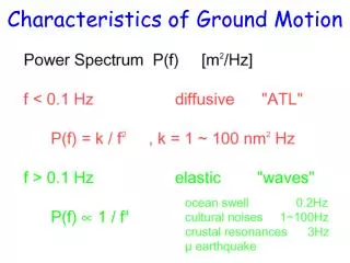
Short term effect of ground motion (1) CMS:measurement [1] Annecy:measurement [2] model A/B/C:ground motion models [3] model B10 (black): model B with 10x more noise for the range >2 Hz (D. Schulte) Ground motion model used for simulations: Real spectrum for short time scales (<1min) [1]: ATL law for long time scales (>1min) [4]: with T=time interval between measurements, L=distance between measurement points [1] A. Kuzmin, Technical Report EDMS Nr. 1027459, CERN, 2009 [2] B. Bolzon, PhD Thesis, Université de Savoie, 2007 [3] International Linear Collider Technical Review Committee: Second Report, SLAC Report-606 (2003) [4] V. Shiltsev, PRSTAB 13, 094801 (2010)
Short term effect of ground motion (2) nom. LHC, 4 TeV, β*=60 cm HLLHCV1.0, 7TeV, β*=15 cm • offset at IP • and • similar effects for nominal LHC than • HL-LHC εn,LHC=2.5 μm εn,HLLHC=1.6 μm Simulation results: J. Pfingstner luminosity loss and • larger effect for HL-LHC than nominal LHC • effect negligible (~10-2) for time range <10s, afterwards assumed correction by the orbit feedback
BPM tolerances for orbit correction (1) IP5 beam 1 SQ2a BPMs in IT/D1 area used for x-scheme/alignment of the beam First estimate of required BPM resolution and number/placement by using an idealized system (results scale linearly with BPM resolution, assumed reference value is +/-0.5 μm) • no field or misalignment errors • treat interaction region as line (from BPMYC.5L5 to BPMYC.5R5) • assume that the orbit is corrected up to BPM resolution (here +/-0.5 μm) at BPMYC.5L5 [*] (=initial condition) and BPMYC.5R5 (=matching constraint end of line) • use perturbed BPM readings to match x-scheme and record resulting orbit YC.5R5 SQW1 WC4 WD4 YY4 YY4 WD4 WC4 SQ1 YC.5L5 SQ2b [*] assume thus z=+/- 0.5 μm => Jz=z2/β=> z=(βJz)1/2cos(φz), z’=(Jz/β)(sin(φz)+αcos(φz)), with Jz∈ [0,Jz] and φz∈ [0,2π]
BPM tolerances for orbit correction (2) Observables: z, z’ at IP and z at crab cavities Comments/Studies: • linear system => z/z’ at IP/crab cavities scales linearly with BPM precision • use all BPMs except one to match orbit • BPMs closest to IP most effective to constraint orbit at IP
BPM tolerances for orbit correction (3) all no BPMWD4* • use all BPMs except one to match orbit (continued) • BPMs closest to crab cavities most effective to constraint orbit at location of crab cavities • use selection of BPMs • same performance using only 3x4 BPMs around IP (BPMSQW1*,BPMSQ1,BPMSQA2) and 2x4 around crab cavities (BPMWD4*,BPMYY4), explicitly no BPMSQB2* (LR bb encounter) and BPMWC4* • x2 worse orbit at position of crab cavities using only BPMSQW1*,BPMSQ1* and BPMWD4*,BPMYY4* (no BPMSQA2*)
Misalignment correction (1) • corrector strength • maximum orbit in triplet (aperture) D2 … 10.0 1.5 Observables: Relative transverse movement of the triplet per year: +/-0.5 mm • misalignment of the triplet by +/-0.5 mm (uniform distribution) and correction with the MCBX* (2.5/4.5 Tm) and MCBRD* (8 Tm) correctors Correction Schemes: • MCBX* and two MCBRD • all correctors, but limit strength in MCBRDs MCBRD E. Todesco For x-scheme: crossing plane: MCBX1: 0.4 Tm, MCBX2: 0 Tm MCBX3: 2.1 Tm, MCBRD: 4.5 Tm separation plane: MCBX1: 0.15 Tm, MCBX2: 0 Tm MCBX3: 0.24 Tm, MCBRD: 0.14 Tm
Misalignment correction (2) • MCBX* and two MCBRDs • small orbit deviation in triplet (<1.0 mm) • corrector strength within limits
Misalignment correction (3) • all correctors, but limit strength in MCBRD (in order to limit orbit in triplet) • larger orbit deviation in triplet (<1.5 mm) than for case a) • by x2 smaller corrector strength than for case a)
Tolerances on powering of the IT (1) Summary of results of previous studies: A ripple on the current/voltage induces a change in tune, beta-beating, orbit, chromaticity ... In general the changes in beta-beating, orbit and chromaticity are negligible, but the induced tune ripple can be non-negligible. Experiments at the SPS [1,2] suggest that a tune ripple of 10-4 is acceptable while experiences at HERA [3] show that for low frequencies even a tune ripple of 10-5 and for high frequencies 10-4 can lead to significant particle diffusion. Experiment [1,2], theory and tracking studies [4,5] show that several ripple frequencies are much more harmful than a single one. Typical ripple frequencies lie between 5-1200 Hz [1,2,3] [1] X. Altuna et al., CERN SL/91-43 (AP) [2] W. Fischer, M. Giovannozzi, F. Schmidt, Phys. Rev. E 55, Nr. 3 (1996) [2] O. S. Brüning, F. Willeke, Phys. Rev. Lett. 76, Nr. 20 (1995) [3] O. S. Brüning, Part. Acc. 41, pp. 133-151 (1993) [4] M. Giovannozzi, W. Scandale, E. Todesco, Phys. Rev. E 57, Nr.3 (1998) First estimate by calculating the tune ripple induced by a uniformly distributed error on the current, which should stay below 10-4
Tolerances on powering of the IT (2) Proposed powering scheme HL-LHC: Ballarino, 4th LHC Parameter and Layout Committee
Tolerances on powering of the IT (3) • +/-di uniformly distributed error Simulation using MAD-X, HLLHCV1.0 optics: • uniformly distributed (independent) errors on current => gradient error: itok = kmax/(17.3) kmax=0.599599999902e-02 di = 1e-06 +/-1 ppm ripple on current dk1l5 = 2*itok*17.3*di*(ranf()-0.5) dkt3l5 = 2*itok*2.0*di*(ranf()-0.5); … kqx1.L5 := kqx10.L5 + dk1l5 kqx2a.L5 := kqx2a0.L5 + dk2l5 ; kqx2b.L5 := kqx2b0.L5 + dk2l5 + dkt2bl5 ; kqx3.L5 := kqx30.L5 + dk1l5 + dkt3l5 ; … • optics: round (β*=15 cm), flat (β*=7.5/30 cm), sround (β*=10 cm), sflat (β*=5.0/20 cm) powering scheme
Tolerances on powering of the IT (4) • linear dependence on relative current error (note: ) • almost no effect from trims for Q3 and Q2b • dependence on β*: apply +/- 1.0 ppm current ripple and and x 1.9 x 1.5 x 1.25 and x 1.0 alternate xing+ anti-sym. triplet similar result for Qyand beam 2
Conclusion • Ground motion in IT/D1 area (<10s): • effect on orbit similar to the LHC (but smaller beam spot size for the HLLHC) and negligible in the range <10 s • BPM tolerances: • orbit at the location of the crab cavities negligible (in the range of 2 μm for a resolution of +/-0.5 μm) • the simplified model used shows that for a luminosity loss <1%, a BPM resolution of +/-1.25 μm would be needed assuming εn=2.0 μm, β*=0.15 m [*] • a matching of the IP is also possible with only a subset of BPMs with an eventual loss in precision (note: same precision for 1x4 BPM less around the IP and 1x4BPM less around crab cavities) [*]linear system, thus δIP,max=const*(BPM resolution)
Conclusion • Misalignment Correction: • Two feasible correction schemes: • MCBX*+2 MCBRD correctors: minimization of the orbit in the IT • all correctors (MCBX*+4 MCBRD, limit on MCBRD strength): minimization of corrector strength • Tolerances on powering of the IT: • uniformly distributed relative current error of +/-1.0 ppm leads to a tune ripple of 4.0-8.0x10⁻⁴ depending on the optics • scaling with beta function according to (1/β1*+1/β2*) and linear scaling withrelative error
Open questions? • Ground motion in the IT/D1 area: • here misalignment = misalignment of the cryostat. Movement of the magnet inside cryostat? • BPM tolerances: • precision (reproducibility of measurements) during one fill? • effect of gradient errors? • effect of longitudinal misalignmentof the BPMs(high z’, thus small longitudinal misalignment results in relatively large difference orbit) and also the triplet? • Tolerances on powering of the IT: • acceptable tune ripple? • frequencies of ripple? • if tolerances on ripple turn out to be too tight, possible compensation like in HERA?
Ground motion measurements LHC IT H. MainaudDurand 4th HL-LHC PLC meeting Leveling measurements once per year during the winter shutdown Relative measurements every 10s
Simulation method ground motion Simulation method [3], [4]: • Ground motion and thus misalignment of the IT is described as a superposition of sine and cosine like oscillations with the frequency and wavelength given by the 2-d power spectrum • The effect of the misalignment on the closed orbit is calculated by using the orbit response matrix : • The effect of the misalignment on the orbit (expressed by the sensitivity function ) is first calculated for each frequency and wavelength individually • All waves are assumed to be independent, thus the rms closed orbit offset is given by: [3] A. Sery and O. Napoly, Influence of ground motion on the time evolution of beams in linear colliders, Phys. Rev. E, 53:5323 (1996) [4] J. Pfingstner, Mitigation of ground motion effects via feedback systems for the Compact Linear Collider, PhD Thesis (2012)
BPM tolerances for orbit correction (1) R. De Maria
BPM tolerances for orbit correction (4) • use selection of BPMs • same performance using only BPMSQW1*,BPMSQ1,BPMSQA2 and BPMWD4*,BPMYY4 (no BPMSQB2*, no BPMWC4*) • x2 worse orbit at position of crab cavities using only BPMSQW1*,BPMSQ1* and BPMWD4*,BPMYY4* (no BPMSQA2*) • possible to match x-scheme using only BPMSQ1* and BPMYY4*, but worse orbit at IP and location of crab cavities and a max. orbit excursion of up to 0.45 mm
Misalignment correction (4) • all correctors, but limit the maximum orbit in the triplet • slightly smaller orbit deviation (<1.1 mm) than for case b) • but x2 larger corrector strength than for case b) (MCBX1<1.5 Tm, MCBX2<2 Tm, MCBX3<1.0 Tm, MCBRD<0.1 Tm)
Misalignment correction (4) • only MCBX* and xIP,b1-xIP,b2=sep, pxIP,b1-pxIP,b2=x-angle • smaller orbit in triplet (xco<12 mm, yco<1.2 mm) • but too high corrector strength! (MCBX1<14 Tm, MCBX2<10 Tm, MCBX3<3.0 Tm)
Tolerances on powering of the IT (1) Effect on beta-beating, orbit and chromaticity for round optics (15 cm β*) and +/-1.0 ppm ripple on current : max. beta-beating (complete ring) closed orbit IP5, beam 1 chromaticity
Tolerances on powering of the IT (3) Simulation setup for MAD-X: • uniformly distributed ripple on current => gradient ripple: itok = kmax/(17.3); (kmax=0.599599999902E-02) di = 1e-06; (ripple on current) dk1l5 = 2*itok*17.3*di*(ranf()-0.5); (+/-di uniformly distributed error) kqx1.L5 := kqx10.L5 + dk1l5 ; kqx2a.L5 := kqx2a0.L5 + dk2l5 ; kqx2b.L5 := kqx2b0.L5 + dk2l5 + dkt2bl5 ; kqx3.L5 := kqx30.L5 + dk1l5 + dkt3l5 ; kqx1.R5 := kqx10.R5 + dk1r5 ; kqx2a.R5 := kqx2a0.R5 + dk2r5 ; kqx2b.R5 := kqx2b0.R5 + dk2r5 + dkt2br5 ; kqx3.R5 := kqx30.R5 + dk1r5 + dkt3r5 ; • simulation for 104 different seeds powering scheme (same for IR1)