
Humidity
E N D
Presentation Transcript
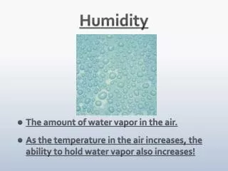
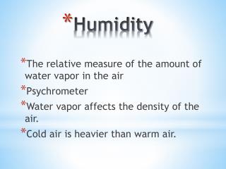
Humidity • Humidity sensors- Vapour pressure and dew point temperature- Soil moisture sensors- Leaf wetness sensors
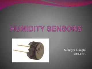
Electrical RH Sensors • Capacitance changes with RH – thin layer of hygroscopic polymer between two capacitance plates - almost linear- ~2% accuracy to 90% RH, then ~3%
Alsoa thermistor in this RH/Temperature sensor Electrical RH Sensors • Resistance changes with RH… a “hygristor” - less accurate - responds differently to increasing versus decreasing RH (hysteresis error)
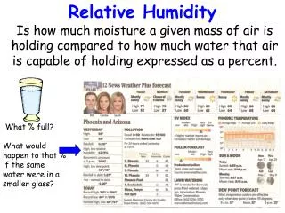
Curve shows max possible vapour pressure What is relative humidity (RH)? RH in % = current VP Max possible VP X 100 Current conditions plotted as “A”T = 35 C, VP = 28 hPa RH = (28 / 56) x 100 = 50% “B” is max possible vapour pressure at 35 C = 56 hPa
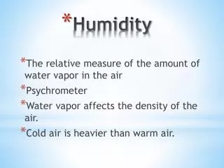
RH depends on vapour content and temperature, so temperature variations will change RH even when the vapour pressure of the atmosphere is constant.
Let’s check to see how much the actual water content of the atmosphere changed from 6am to 3pm on this day, by computing the vapour pressure (e) at the two times. At 6am: T=10C, RH = 90% Max e @ 10C = 12.3 hPaSo e = 0.90 x 12.3 =11.1hPa At 3pm: T=25C, RH = 35% Max e @ 35C = 31.7 hPaSo e = 0.35 x 31.7 =11.1hPa
Exposure of Humidity Sensors • Shield RH sensors – must be at correct air temperature to give correct RH • Filters on RH sensors- keep dry - keep clean so they do not lower the ventilation rate and increase the risk of radiation error
The concept of “dew point temperature” The temperature to which air must be cooled to initiate condensation. Current conditions are plotted at “A”…T = 35 C, VP = 28 hPa Imagine we cool the air along the path A –D. At “D” we reach the max possible VP line, which is where condensation will begin.The temperature at “D” is the dew point temperature, about 21 C.
RH = es@Td / es@T = 16.7 hPa / 28.4 hPa = 0.588 or 58.8% es@Td = RH x es@T = 0.724 x 19.9 hPa = 14.4 hPaUsing SVP table, 14.4 hPa matches 12.4 C, which is Td. • Since e = es@Td, & RH = e / es@T, then RH =es@Td / es@T • 1. The weather channel shows the following conditions at Halifax airport: T = 23.2 C, Dew point = 14.7 C • What is the relative humidity? • 2. Your T/RH probe reads T = 17.4 C, RH = 72.4% • - what is the dew point temperature?
Radiation absorption hygrometers • Allow air to flow between a radiation source and a detector. • Choose source emission at a wavelength that is absorbed by water vapour (usually in the ultra-violet or infra-red regions) • This is a “Krypton Hygrometer” • Krypton lamp in one head emits U.V. radiation that is absorbed by water vapour. • U.V. detector in other head senses the fluctuating concentration of water vapour in air that blows through the gap between U.V. emitter and detector. Source Air flow Detector U.V. emitter U.V. detector
Radiation absorption hygrometers used for Eddy Covariance flux measurements • Can detect rapid fluctuations in water vapour • Used to make measurements of evaporation of water from land or water surfaces into the air, in combination with fast response wind sensor. • E = Vapour concentration x Vertical wind component = kg/m3 x m/s = kg evap /m2 each second. • Technique can also be used with fast response infra-red absorption CO2 sensor to get CO2 flux. Fast response wind sensor Fast response H20 or CO2 sensor
Soil Moisture Time domain reflectometry (TDR) Signal sent down probes bounces back (reflects) when it reaches the ends of the probes. Time required to travel down and back depends on the moisture content of the material between the probes. Can insert the probes…- vertically, to average over a depth of soil- horizontally, to average over a horizontal layer- diagonally, for combined vertical and horizontal average. (Strangeways – Fig. 9.9)
Leaf Wetness Sensors • Grid of interlaced, but non-contacting, conducting fingers • Presence of rain or dew water changes the resistance or capacitance between the fingers wetness signal
Decagon leaf wetness sensor Growers use data on duration of leaf wetness, and temperature during the wet period, to decide if a fungicide spray is needed. Results in fewer sprays, and lower chemical costs… a win for both the grower and the environment.
Calibration of RH probes The wet and dry bulb psychrometer. Cooling of the wet bulb by evaporation is related to the dryness of the air (drier air, more cooling). So e = eSW - 0.65(T-Tw) Suppose you measure a dry bulb temperature of 20.2 C and a wet bulb of 17.3 C. What is the RH?
A high-quality “Assman” shielded and ventilated psychrometer. Air is drawn past the thermometer bulbs by a spring-driven fan Thermometer bulbs are shielded from radiation
Calibration requires generation of known water vapour content in air (Fig 5-17)
Suppose you take a psychrometer or other well-calibrated RH sensor that is shielded & ventilatedto the field to check a T/RH probe at your weather station. • But it’s a calm day, and the weather station probe is in an unventilated shield, so it is suffering a radiation error, and is reading a higher temperature than your calibration unit. • If the RH sensor in the weather station probe is working correctly, why won’t it give the same value as the RH from your calibration unit? • How could we still check the accuracy of the weather station RH sensor in this situation? (Hint: the actual VP is unaffected by a radiation error.) Can we check the accuracy of the station T-sensor?
Ventilated psychrometer in a “Stevenson Screen” thermometer shield Fan on roof sucks air through the tube that surrounds the thermometers.
Bare grids lack sensitivity… • Coat with latex paint (transmits water to grid for good response) • Allows colour adjustment to match drying of leaves. Lighter visible colour than real leaves needed because paints do not match the high reflectivity of leaves in solar infra-red wavelengths.